Inhaltsverzeichnis
Einführung der Guillotineschere
Der Tafelschere bietet im Vergleich zur Schwingbalkenschere eine höhere Effizienz, Präzision und Zuverlässigkeit, da sie Spiel in der Struktur eliminiert und die Anpassung des Scherwinkels ermöglicht.
Beim Schneiden von breiten, schweren Platten oder hochfesten dünnen Platten kann es bei der Tafelschere jedoch zu Problemen kommen, beispielsweise zu einer Verformung der Maschine, die die Schnittgenauigkeit beeinträchtigt.
Die meisten Forschungsarbeiten auf diesem Gebiet konzentrieren sich auf die Auswirkungen der Scherparameter auf die Genauigkeit, die Gestaltung und Automatisierung des Steuerungssystems oder die Simulation des Scherprozesses anhand diskreter Punkte.
Es gibt jedoch nur begrenzte Forschung zur Analyse mechanischer Eigenschaften und zur Strukturoptimierung von Schlagschere.
Dieser Artikel soll diese Lücke schließen, indem er die statischen und dynamischen Eigenschaften der Werkzeugmaschine analysiert und den Plattenscherprozess simuliert. Durch diese Analyse werden kontinuierliche Scherdaten gewonnen und ein Optimierungsschema vorgeschlagen.
Statische Analyse
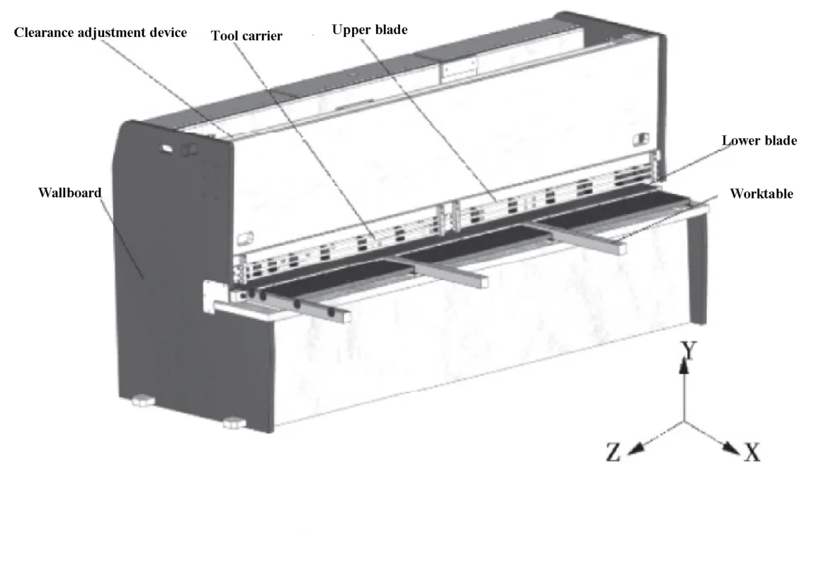
In Abbildung 1 ist ein Strukturmodell einer 6 x 3200 NC-Tafelschere dargestellt. Während des Betriebs passt die von der Rollenspindel angetriebene Gegenhaltevorrichtung die Schnittlänge an. Der Presszylinder wird dann durch die Scherplatte zusammengedrückt.
Sobald die Schneidparameter wie Klingenabstand und Scherwinkel eingestellt sind, treiben die Hydraulikzylinder an beiden Enden die oberen und unteren Klingen an, um den Plattenschneidevorgang abzuschließen.
Bei der Simulationsanalyse werden die Übergangsrundung und das Gewindeloch nicht berücksichtigt und ein vereinfachtes dreidimensionales Modell in eine Software zur Finite-Elemente-Analyse importiert. Die beiden Seiten der oberen Werkzeugauflage werden mit Einschränkungen fixiert und es wird ein Bindungskontakt hergestellt, um das Schweißen und die Gewindefixierung der oberen Werkzeugträgerteile zu simulieren.

Nach der Formel von Norsali:

In der Formel:
σb – Festigkeitsgrenze der zu schneidenden Platte;
δs – Duktilität des zu schneidenden Bleches;
h – Dicke des zu schneidenden Blechs;
α – Scherwinkel;
x, y, z – Der Biegekraftkoeffizient, der relative Wert des Seitenspiels der Schneide und der Presskoeffizient.
Die vertikale Scherkraft (P1) wird mit Formel (1) auf 212,8 kN berechnet, während die horizontale Scherkraft (P2) auf 30% der vertikalen Scherkraft bzw. 63,8 kN geschätzt wird. Sowohl die vertikale als auch die horizontale Scherkraft werden auf den oberen Turm angewendet und mit ANSYS Workbench berechnet.
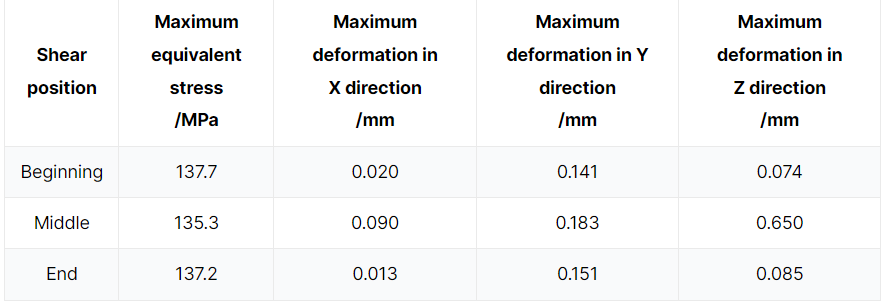
Die Verformung in jeder Richtung zu Beginn, in der Mitte und am Ende des Scherens wird verglichen und analysiert. Wie aus Tabelle 1 hervorgeht, ist die Verformung des oberen Wagens in Y-Richtung am größten, und die Verformung in X- und Z-Richtung kann im Vergleich dazu als vernachlässigbar angesehen werden.
Die Start- und Endpositionen der Verformung in Y-Richtung sind ungefähr gleich und viel geringer als die Mittelposition. Während des Schervorgangs zeigt die Verformung des oberen Werkzeughalters eine konkave Tendenz.
Tabelle 1 Maximale äquivalente Spannung und maximale Verformung in X-, Y- und Z-Richtung des oberen Werkzeughalters

In den Abbildungen 2 und 3 ist die maximale Vergleichsspannung in der Mitte bzw. die maximale Verformung in Y-Richtung dargestellt.

Durch Analyse von Tabelle 1 und Abbildungen 2 und 3 lässt sich feststellen, dass die äquivalente Spannung des oberen Werkzeugträgers zu Beginn des Schervorgangs am höchsten ist. Diese Spannung befindet sich an der Position des Hydraulikzylinders und hat einen Wert von 137,7 MPa, der niedriger ist als die Streckgrenze von 235 MPa für den oberen Werkzeugträger.
In der Mitte des Schervorgangs wird die maximale Verformung des oberen Werkzeughalters in Y-Richtung an der hinteren Stützplatte B mit einer Größe von 1,183 mm beobachtet. Gleichzeitig beträgt die Verformung der Klinge in Y-Richtung 0,346 mm, was weniger als 1 mm ist und die erforderlichen Anforderungen erfüllt.
Transiente dynamische Analyse
Bei der dynamischen Simulation wird ein Schieber an der Ausgangsposition des Obermessers platziert und konstant mit einer vorgegebenen Geschwindigkeit der Scherkraft ausgesetzt. Die Bewegung des Schiebers dient zur Simulation des Blechschervorgangs.
Da der Schieber nur Scherkräfte überträgt, ist er so eingestellt, dass er reibungslosen Kontakt mit dem Obermesser hat. Während des Schneidens des Blechs ist der Kontakt zwischen dem Obermesser und dem zu schneidenden Blech in Abbildung 4 dargestellt. Die Kontaktlänge (s) beträgt 8:1.

Um die Berechnung zu vereinfachen, wird angenommen, dass die Scherkraft gleichmäßig über eine rechteckige Fläche mit der Länge (s) und Breite (t) der Klinge verteilt ist. Infolgedessen wird der Schieber als Quader mit der gleichen Länge (s) und Breite (t) modelliert, wie in Abbildung 5 dargestellt.

Durch Berechnung der maximalen äquivalenten Spannung und der maximalen Verformung in Y- und Z-Richtung an jeder Position werden die Ergebnisse in Tabelle 2 dargestellt. Der Trend der Verformung und Spannung des oberen Werkzeughalters während des Schervorgangs ist in Abbildung 6 dargestellt.
Tabelle 2 Maximale Vergleichsspannung und maximale Verformung in Y- und Z-Richtung des oberen Werkzeugträgers unter jeder Laststufe
| Schritt laden | Maximale Vergleichsspannung | Maximale Verformung in Y-Richtung | Maximale Verformung in Z-Richtung |
| /MPa | /mm | /mm | |
| 1 | 138.1 | 0.265 | 0.181 |
| 2 | 153.2 | 0.38 | 0.33 |
| 3 | 158.4 | 0.403 | 0.386 |
| 4 | 159.2 | 0.469 | 0.426 |
| 5 | 157.5 | 0.592 | 0.463 |
| 6 | 153.8 | 0.571 | 0.454 |
| 7 | 148.1 | 0.58 | 0.461 |
| 8 | 150.3 | 0.635 | 0.478 |
| 9 | 153.7 | 0.543 | 0.458 |
| 10 | 154.9 | 0.477 | 0.446 |
| 11 | 153.2 | 0.482 | 0.425 |
| 12 | 141.8 | 0.358 | 0.336 |
| 13 | 136.4 | 0.25 | 0.175 |
Wie aus Tabelle 2 und Abbildung 6 ersichtlich, ändert sich die Verformung des oberen Werkzeughalters mit der Änderung der Scherposition. Die Verformung ist in der Mitte signifikant und auf beiden Seiten relativ klein und symmetrisch, was mit den Ergebnissen der statischen Simulation übereinstimmt.
Die maximale Verformung des oberen Werkzeughalters in Y- und Z-Richtung tritt in der Laststufe 8 auf und beträgt mit 0,635 mm bzw. 0,478 mm Werte, die weniger als 1 mm betragen.
Die maximale Vergleichsspannung wird in Laststufe 4 gefunden und weist einen Wert von 159,2 MPa auf, der niedriger ist als die Streckgrenze von 235 MPa für den oberen Werkzeughalter.

Die Abbildungen 7, 8 und 9 zeigen die maximale Verformung und die maximale äquivalente Spannung in Y- bzw. Z-Richtung.


Aus den Abbildungen 7, 8 und 9 ist ersichtlich, dass die maximale Verformung des Oberwagens in Y-Richtung bei Schaufel C auftritt, während die maximale Verformung in Z-Richtung bei Schaufel D auftritt. Beide Verformungen betragen weniger als 1 mm und erfüllen damit die Konstruktionsanforderungen.
Die maximale Vergleichsspannung tritt an Position E des oberen Werkzeugträgers unter dem Einfluss des Hydraulikzylinders auf. Die Belastung der Klinge ist minimal und weist eine gute Steifigkeit auf.
Rahmenmodalanalyse
Bei der Modalanalyse werden die vier Basen des Rahmens fixiert und mit Einschränkungen an ihrem Platz gehalten. Als Modusextraktionsmethode wird die Block-Lanzos-Methode ausgewählt und die Anzahl der erweiterten Modi auf 4 gesetzt, um die ersten vier Eigenfrequenzen der Rahmenstruktur zu ermitteln.
Die vier Schwingungsmodi sind in Abbildung 10 dargestellt und Tabelle 3 zeigt die Eigenfrequenzen, Amplituden und Modalformen der vier strukturellen Schwingungsmodi.

| Befehl | Frequenz | Amplituden | Schwingungsart |
| /Hz | /mm | ||
| 1 | 19.02 | 1.77 | Die Frontplatte ist in X-Richtung nach vorne gebogen |
| 2 | 24.98 | 0.81 | Der obere Teil des Rahmens biegt und schwingt in Z-Richtung |
| 3 | 28.96 | 6.09 | Der untere Stützbalken ist entlang der X-Richtung nach vorne gebogen |
| 4 | 42.66 | 1.53 | Die Frontplatte wird in X-Richtung hin und her gebogen |
Anhand von Abbildung 10 und Tabelle 3 ist ersichtlich, dass die Schwingungsverformung des Rahmens in erster Linie die Frontplatte und den unteren Stützbalken beeinflusst und erhebliche Vibrationen und Geräusche verursacht. Bei einer Frequenz von 19,02 Hz ist die Amplitude der Frontplatte höher, was sich negativ auf den Schervorgang auswirken und dessen Genauigkeit verringern kann.
Die Scherfrequenz der NC-Guillotineschere beträgt jedoch 9-mal pro Minute, was deutlich unter der Eigenfrequenz erster Ordnung liegt und den Anforderungen für den Normalbetrieb entspricht.
Es ist wichtig, den Einfluss externer Vibrationsquellen während des Arbeitsprozesses zu minimieren, um übermäßige Vibrationsverformungen zu vermeiden.
Optimierungsdesign
Die Analyse der statischen und dynamischen Eigenschaften des Scherprozesses zeigt, dass die Verformung des oberen Revolvers während des Scherens eine konkave Tendenz aufweist, die sich auf den Grat und die Maßgenauigkeit des Schnitts auswirken und die Gesamtqualität des Scherens verringern kann.
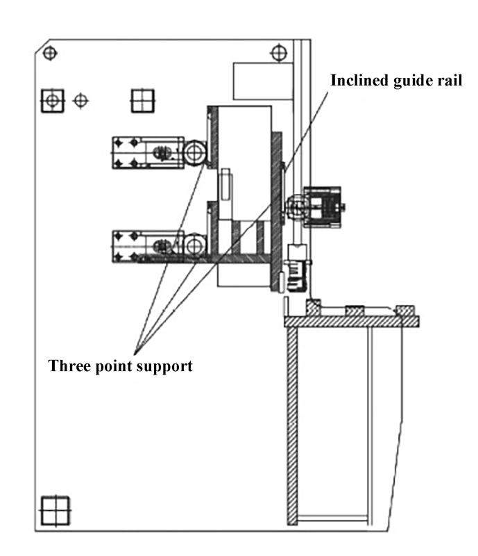
Um die Schnittqualität zu verbessern, kann der Blattabstand in den Schnittparametern angepasst werden, um die Positionssteifigkeit des oberen Werkzeugträgers zu erhöhen. In diesem Artikel wurde eine dynamische Blattabstandseinstellungsvorrichtung mit Schrägführung entwickelt, wie in Abbildung 11 dargestellt.


