Gracias por usar elmi Manual de fuente láser de fibra de 40000 WRecopilamos este documento para usted con el fin de garantizar un uso y mantenimiento adecuados del láser.
Tómese el tiempo necesario para leer y comprender esta Guía del usuario y familiarizarse con las instrucciones de funcionamiento y mantenimiento antes de utilizar el producto. Recomendamos encarecidamente que el operador lea la Sección 2 titulada “Información de seguridad” antes de utilizar el producto.
Esta Guía del usuario debe permanecer con el producto para brindarle a usted y a todos los futuros usuarios y propietarios del producto información importante sobre su funcionamiento, seguridad y otros aspectos.
En el documento, señalamos con subrayado las partes a las que debe prestar especial atención. Tenga en cuenta esta información para evitar daños innecesarios.
Tabla de contenido
Capítulo 1: Descripción de la característica
Serie MFMC CW Láser de fibra Los productos proporcionan una amplia gama de longitudes de onda de 1060 nm a 1100 nm. Los láseres están refrigerados por agua y no requieren mantenimiento, tienen una eficiencia de conexión de más de 30% y brindan alta eficiencia, alta confiabilidad y alto rendimiento.
La serie de láseres de fibra CW MFMC de Maxphotonics son productos láser de clase 4 y están diseñados y probados con seguridad. Si sigue esta Guía del usuario y aplica prácticas de seguridad adecuadas para el uso del láser, será un dispositivo seguro y confiable.
La luz láser presenta características únicas que pueden suponer riesgos de seguridad. Por lo tanto, la luz láser no se puede asociar normalmente con otras fuentes de luz y todos los operadores y las personas que se encuentren cerca del láser deben ser conscientes de estos riesgos especiales.
Para garantizar el funcionamiento seguro y el rendimiento óptimo del producto, siga todas las advertencias e instrucciones de seguridad de esta guía durante el proceso de operación, mantenimiento y servicio y no desmonte el dispositivo.
Este producto no contiene piezas, equipos ni conjuntos que el usuario pueda reparar. Los láseres que se desmonten sin autorización no estarán sujetos a garantía.

Capítulo 2: Información general de seguridad
1-Convenciones de seguridad
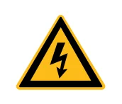
ADVERTENCIA: Se refiere a un posible peligro eléctrico para el cuerpo humano. Requiere un procedimiento que, si no se sigue correctamente, puede provocar daños corporales a usted y/o a otras personas.
No continúe más allá de la señal de ADVERTENCIA hasta que comprenda y cumpla completamente las condiciones requeridas.

PRECAUCIÓN: Hace referencia a un peligro potencial del producto. Requiere un procedimiento que, si no se sigue correctamente, puede provocar daños en el producto o en sus componentes. Para garantizar el uso normal del equipo, no infrinja los requisitos de la señal de PRECAUCIÓN.
NOTA :
◎ Este dispositivo está clasificado como un instrumento láser de clase IV de alta potencia. Puede emitir una potencia media de hasta 3000 W desde 1060 nm hasta 1100 nm. Este nivel de luz puede provocar daños en los ojos y la piel. A pesar de que la radiación es invisible, el haz puede provocar daños irreversibles en la retina. Este instrumento no incluye gafas de seguridad para láser, pero se deben utilizar en todo momento mientras el láser esté en funcionamiento.
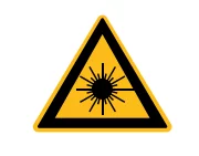
ADVERTENCIA: Se refiere a un posible peligro de láser. El símbolo representa la radiación láser. El símbolo está pegado en el extremo de salida del láser.
SIN SÍMBOLO
IMPORTANTE: Se refiere a cualquier información relacionada con el funcionamiento del producto. No pase por alto esta información.
NOTA :
◎ Este dispositivo está clasificado como un instrumento láser de clase IV de alta potencia. Puede emitir una potencia media de hasta 40/50 KW desde 1060 nm hasta 1100 nm. Este nivel de luz puede provocar daños en los ojos y la piel. Este instrumento no incluye gafas de seguridad para láser, pero se deben utilizar en todo momento mientras el láser esté en funcionamiento.
Utilice gafas de seguridad láser adecuadas al operar este dispositivo.
2-Protección láser
1. Requisitos de protección láser
Debe utilizar gafas protectoras de seguridad mientras opera el láser y seleccionarlas de forma racional según la longitud de onda del láser. Si el dispositivo es un láser sintonizable o un producto Raman, emite luz en un rango de longitudes de onda y el usuario final debe confirmar que las gafas protectoras de seguridad láser utilizadas protegen contra la luz emitida por el dispositivo en todo su rango de longitudes de onda.
2. Proveedores de equipos de protección láser
Maxphotonics le recomienda materiales o equipos proporcionados por los siguientes proveedores de equipos de protección láser, incluidos LaserVision USA, Kentek Corporation, Rochwell Laser Industries, etc. Toda la información de los proveedores es proporcionada por Maxphotonics solo para su comodidad, por lo que Maxphotonics no asume ninguna responsabilidad por cualquier problema causado por el uso de los productos de los proveedores mencionados anteriormente.
3-Estándar de referencia
Emisión de compatibilidad electromagnética:
EN IEC 61000-6-4:2019
CISPR 16-2-1
CISPR 16-2-3
Rendimiento antiinterferencias en compatibilidad electromagnética:
EN IEC 61000-6-2:2019
EN 61000-4-2:2009
EN 61000-4-3:2020
EN 61000-4-4:2012
EN 61000-4-5:2014+A1:2017
EN 61000-4-6:2014
EN 61000-4-11:2020
Seguridad láser:
EN 60825-1:2014+A11:2021
Título 21 del Código de Reglamentos Federales (CFR) 1040.10
Seguridad del sistema eléctrico:
EN 60204-1:2018
NOTA:
◎ El rendimiento del láser MFMC de Maxphotonics cumple con los requisitos de certificación EMC de la CE y los requisitos EMC especificados en la "Directiva EMC" del mercado europeo. Cumple con la norma "EMC" EN 61000-6-4 sobre emisiones y los requisitos antiinterferencias EN 61000-6-2.
◎ De acuerdo con las normas y requisitos nacionales pertinentes, el láser debe clasificarse según su potencia de salida y longitud de onda. Todos los productos láser de la serie MFMC con alta potencia pertenecen a productos de clase 4 (según la sección J,1040.10 (d) de la Parte Ⅱ, 21 CFR).
◎ Según las normas de la UE, el equipo pertenece a un instrumento de clase 4 (según el artículo 9, EN 60825-1).
4-Instrucciones generales de seguridad
1. Reflexión especular
A menudo se generan numerosos rayos láser secundarios en distintos ángulos en el puerto de salida del láser. Estos rayos divergentes se generan cuando el rayo primario del láser se refleja en una superficie lisa y se denominan reflexiones especulares. Aunque estos rayos secundarios pueden ser menos potentes que la potencia total emitida por el rayo primario, la intensidad puede ser lo suficientemente grande como para causar daños en los ojos y la piel, así como en la superficie de los materiales.
ADVERTENCIA:
◎ ¡Debe tener cuidado para evitar/minimizar los reflejos especulares ya que estas radiaciones láser son invisibles!
2.Instrucciones de seguridad de los accesorios
Los elementos fotosensibles integrados en los accesorios ópticos relacionados con el láser pueden resultar dañados por la exposición al láser, como por ejemplo: cámaras de vídeo, fotomultiplicadores y fotodiodos. Se debe prestar atención a la protección de los dispositivos relacionados.
ADVERTENCIA :
◎ La luz láser MFMC de Maxphotonics es lo suficientemente potente como para cortar o soldar metal, quemar la piel, la ropa y la pintura. Además, esta luz puede encender sustancias volátiles como alcohol, gasolina, éter y otros disolventes. Durante el proceso de funcionamiento, los materiales inflamables que rodean al láser deben aislarse.
3. Instrucciones de funcionamiento óptico
Le recomendamos encarecidamente que lea los siguientes procedimientos antes de utilizar el láser:
1. Nunca mire directamente al puerto de salida del láser cuando el dispositivo esté encendido.
2. Evite colocar el láser y todos los componentes de salida óptica a la altura de los ojos.
3. Equipado con carcasa de rayo láser.
4. Asegúrese de quitar la cubierta trasera del cabezal de salida del láser antes de encender el láser; de lo contrario, provocará daños irreversibles en la salida de fibra del láser.
cabeza.
5. Asegúrese de que todo el equipo de protección personal sea adecuado para la potencia de salida y el rango de longitud de onda del láser.
6. Utilice el láser en una habitación con acceso controlado mediante cerraduras de puertas. Coloque señales de advertencia. Limite las áreas de seguridad para operar el láser.
7. No utilice el láser en entornos oscuros.
8.No encienda el láser sin una fibra de acoplamiento óptico o un conector de salida óptica.
9. Realice la puesta en servicio, la calibración y el enfoque a baja potencia de salida y luego aumente la potencia de salida gradualmente cuando haya terminado el trabajo de calibración y enfoque.
10.No instale ni desconecte los cabezales de corte ni los colimadores cuando el láser esté activo.
11. Asegúrese de que el láser esté apagado y sin energía antes de instalar o desmontar cabezales de corte o colimadores.
12. Si el equipo se opera de una manera no especificada en este documento, los dispositivos de protección y el rendimiento del equipo pueden verse afectados y la garantía quedará anulada.
PRECAUCIÓN:
◎ La salida del láser se emite a través de una lente con un revestimiento antirreflejo. Si la trayectoria de luz de la etapa posterior de su láser tiene una lente óptica, inspeccione estrictamente la lente del cabezal de salida y la lente de la etapa posterior del láser, y asegúrese de que no haya polvo ni otras impurezas en la lente.
Tenga en cuenta que cualquier accesorio macroscópico puede causar daños extremos a la lente o quemar el láser o cualquier equipo de trayectoria de luz de etapa inversa.
◎ Para obtener instrucciones de limpieza de la lente, consulte la "Guía de inspección y limpieza del conector de fibra óptica".
◎ Cuando el láser está en funcionamiento, pueden formarse trozos de metal calientes o fundidos. Tenga cuidado si se producen residuos durante el funcionamiento.
◎ Al realizar la puesta en servicio y calibración de la salida del láser, debe configurar la salida del láser a un nivel de potencia bajo y luego aumentar gradualmente la potencia de salida durante la verificación de la calidad del punto de luz emitido por el láser a través de un visor infrarrojo.
ADVERTENCIA:
◎ Asegúrese de que el equipo de protección individual cumpla con la potencia de salida y el rango de longitud de onda del láser.
◎ Nunca mire directamente a la fibra óptica ni al colimador y asegúrese de usar gafas protectoras de seguridad en cada operación.
4. Instrucciones de funcionamiento eléctrico
Le recomendamos encarecidamente que lea los siguientes procedimientos antes de utilizar el láser:
1. El voltaje de alimentación del equipo láser es de corriente alterna trifásica de 360-440 V CA, 3P+PE. El equipo láser debe estar correctamente conectado a tierra durante la instalación. Los cables externos del gabinete deben colocarse en canaletas o tuberías metálicas durante la instalación. Preste atención a la seguridad eléctrica durante el uso para evitar lesiones por descarga eléctrica.
2. Al desmontar el láser, desconecte primero la alimentación. Si se produce una lesión eléctrica, se deben tomar medidas correctivas para evitar lesiones secundarias. El proceso de tratamiento correcto es el siguiente: desconecte la alimentación, libere al personal de forma segura, solicite ayuda y acompañe al herido.
3. El equipo no tiene ninguna parte que pueda ser mantenida por operadores, y todas las operaciones de mantenimiento deben ser realizadas por los profesionales de Maxphotonics.
4. Para evitar descargas eléctricas, no retire la carcasa, no separe el láser sin permiso y no dañe las señales correspondientes. Cualquier producto que se desmonte sin autorización no estará sujeto a garantía.
ADVERTENCIA:
◎ El voltaje de entrada del láser es corriente alterna trifásica (360-440 V CA, 3P+3E), lo que puede provocar riesgo de descarga eléctrica. Todos los cables y cables de conexión pertinentes presentan riesgos potenciales.
5. Condiciones ambientales y precauciones
Para garantizar la seguridad del área de trabajo del láser, se deben utilizar cerramientos adecuados, incluidos, entre otros, los carteles de seguridad del láser y los dispositivos de enclavamiento. Los operadores correspondientes deben recibir formación y exámenes y conocer las especificaciones de seguridad normales para operar el láser. Mientras tanto, es importante que los componentes de salida no se instalen a la altura de los ojos.
Debido a la interacción del láser y el material metálico, se puede producir una radiación de luz ultravioleta o luz visible de alto nivel. Asegúrese de que el láser esté provisto de una cubierta protectora para evitar que la radiación dañe los ojos u otras partes del cuerpo humano.
Le recomendamos que cumpla con las siguientes medidas operativas para prolongar la vida útil del láser:
1. Para garantizar un buen entorno operativo del láser, reducir el riesgo de condensación, reducir la probabilidad de falla y prolongar la vida útil.
Se recomienda encarecidamente configurar la sala con aire acondicionado del láser con antelación. La sala con aire acondicionado debe ser lo suficientemente amplia como para facilitar el mantenimiento interno. Puede garantizar que el espacio libre mínimo alrededor del láser sea de 1,0 m. Si el espacio es limitado, la sala con aire acondicionado debe diseñarse para que sea fácil de quitar e instalar.
2. Es necesario proporcionar suficiente espacio de instalación para el enfriador de agua refrigerado por aire y garantizar un escape suficiente del enfriador de agua. El espacio libre mínimo de la parte superior del ventilador refrigerado por aire es de 1,5 m y la placa lateral del filtro de aire está a 1 m de la pared.
3. Está prohibido colocar la máquina de refrigeración por agua y aire en una sala con aire acondicionado láser. Debido a que la máquina de refrigeración por agua y aire descarga una gran cantidad de aire caliente, la temperatura de la sala aumentará rápidamente y, finalmente, la disipación de calor será deficiente, lo que provocará la alarma de alta presión de la máquina de refrigeración por agua y la alarma de condensación láser.
4. No exponga el láser a un entorno con mucha humedad.
5. El dispositivo está equipado con ventiladores de refrigeración. Asegúrese de que haya suficiente flujo de aire para enfriar el láser. Deben eliminarse en todo momento todos los objetos o residuos que cubran los orificios de ventilación.
6. El funcionamiento a temperaturas más altas acelerará el envejecimiento, aumentará la corriente de umbral y reducirá la eficiencia de la carga. Si el dispositivo se sobrecalienta, detenga las operaciones y comuníquese con Maxphotonics.
7. Asegúrese de que la superficie de trabajo esté bien ventilada. Es posible que se generen gases, chispas y residuos a partir de la interacción entre el láser y la superficie de trabajo, lo que podría suponer un riesgo adicional para la seguridad.
PRECAUCIÓN :
◎ El dispositivo puede dañarse si se utiliza sin precaución.
5-Información adicional de seguridad
Para obtener información adicional sobre la seguridad del láser, consulte la lista abajo:
Instituto de Láser de América (LIA)
13501 Ingenuity Drive, Suite 128
Orlando, Florida 32826
Teléfono: 407 380 1553, Fax: 407 380 5588
Línea gratuita: 1 800 34 LASER
Instituto Nacional de Normas Estadounidenses
ANSI Z136.1, Norma nacional estadounidense para el uso seguro de láseres
(Disponible a través de LIA)
Comisión Electrotécnica Internacional
IEC 60825-1, Edición 1.2
Centro de Dispositivos y Salud Radiológica
21 CFR 1040.10 - Normas de rendimiento para productos emisores de luz
Departamento de Trabajo de los Estados Unidos - OSHA
Publicación 8-1.7 - Directrices para la seguridad del láser y la evaluación de riesgos.
Equipo de seguridad láser
Editorial Laurin
Equipos de seguridad láser y guías de compra
Capítulo 3: Descripción del producto
1-Características
Los láseres de fibra CW de la serie MFSC son láseres compactos, eficientes y de alta calidad desarrollados para aplicaciones industriales. Se aplican principalmente en los campos de punzonado, soldadura, corte, etc.
Características principales:
1、Salida láser de alta calidad
2、Alta potencia, alta eficiencia.
3、Alta confiabilidad, larga vida útil.
4、Paquete compacto y resistente
5、Interfaz de programación de extensión
Aplicaciones:
1. Aplicaciones industriales
2. Investigación científica
Configuración de 2 módulos
Maxphotonics ofrece muchos modos configurables. Este manual le proporcionará instrucciones completas para todos los modos; consulte las secciones 6.3 a 6.6.
3-Códigos de designación de modelos láser
| Lunes, viernes, domingo, miércoles, miércoles, viernes y viernes. 1 – 2 – 3 – 4 – 5 – 6 | ||
| 1 | Código del fabricante | M significa Maxphotonics |
| 2 | Ganancia de medios de la láser | F significa láser de fibra |
| 3 | Modo láser | S significa modo único |
| 4 | Estado del láser | C significa Continuar Onda |
| 5 | Salida máxima fuerza | XXXX W significa la potencia máxima de salida de El láser |
| 6 | Mensaje adicional | Puede ser nulo |
4–Certificación
Maxphotonics certifica que este equipo ha sido probado e inspeccionado exhaustivamente y cumple con las especificaciones publicadas antes de su envío. Al recibir el equipo, verifique que el embalaje y los accesorios no hayan sufrido daños durante el transporte. Si observa algún daño, comuníquese con Maxphotonics de inmediato.
5- Descripción del panel frontal
| Elementos | Descripción de la función |
| ① INTERRUPTOR PRINCIPAL | Interruptor de alimentación principal de 440 V CA del láser |
| ② INTERRUPTOR DE LLAVE | Interruptor de encendido del láser |
| ③ PARADA DE EMERGENCIA | Parada de emergencia |
| ④ INICIO | Iniciar láser (señal de encendido y apagado de hardware) |
| ⑤ ALARMA | Luz de situación anormal de láser |
| ⑥ ACTIVO | Luz de situación normal de láser |
| ⑦ PODER | Luz de encendido del láser |

Descripción del panel posterior 6
| Elementos | Descripción de la función |
| ① Control | Conector de control externo |
| ②ETHERNET | Interfaz de comunicación de red |
| ③SALIDA DE AGUA | Puerto de salida de refrigeración por agua (40kW y 50kW 2 pulgadas) |
| ④AGUA EN | Puerto de entrada de refrigeración por agua (40kW y 50kW 2 pulgadas) |
| ⑤ CA 380 V | Entrada CA 360-440 V CA |

7-Terminal de salida óptica
1. Cabezal de salida óptica
El cabezal de fibra óptica se utiliza de acuerdo con la ventana protectora y se puede reemplazar en caso de sufrir daños. Asegúrese de quitar la tapa negra del cabezal LOE antes de usarlo, que generalmente se coloca con el láser. Consulte el Capítulo 6 "Pautas para la inspección y limpieza de conectores de fibra óptica" para obtener información sobre los suministros y métodos de limpieza de la ventana protectora.
Cabezal de salida óptica (LOE-P, LOE-T) MFMC-40000

Cabezal de salida óptica (LOE-S) MFMC-50000

Capítulo 4: Especificación
1-Parámetros característicos ópticos
| Características | Condiciones de prueba | Mín. | Nombre. | Máximo | Unidad |
| Módulo de operación | CW/modulada | ||||
| Polarización | Aleatorio | ||||
| MFMC-40000 | Potencia de salida CW 100% | 40000 | Yo | ||
| MFMC-50000 | Potencia de salida CW 100% | 50000 | Yo | ||
| Rango de ajuste de potencia de salida | 10 | 100 | % | ||
| Longitud de onda de emisión | 100% en sentido horario | 1070 | 1080 | 1090 | Nuevo Méjico |
| Ancho del espectro (3dB) | 100% en sentido horario | 5 | 8 | Nuevo Méjico | |
| Poder a corto plazo inestabilidad | 100% Tiempo de respuesta >1 hora | ±1 | ±2 | % | |
| Energía a largo plazo inestabilidad | 100% CW >24 horas | ±2 | ±3 | % | |
| Calidad del haz (BPP) | Núcleo de fibra de salida diámetro 100um | 4 | 5.5 | mm x señor | |
| Núcleo de fibra de salida diámetro 150um | 5.5 | 6.5 | |||
| Núcleo de fibra de salida diámetro 200um | 8 | 10 | |||
| Tiempo de encendido del láser | 150 | 200 | microsegundos | ||
| Tiempo de apagado del láser | 150 | 200 | microsegundos | ||
| Tasa de modulación | Salida 100% | 5 | kilohercios | ||
| Potencia del láser guía rojo | 400 | tuW | |||
| Longitud del cable de fibra de alimentación | 20 | metro | |||
| Tamaño del núcleo de la fibra de alimentación | 150 (100/200 se pueden personalizar) | ||||
| Alimentación de cable de fibra radio de curvatura | 200 | ||||
| Formulario de salida | LOE | ||||
2-Parámetros Característicos Generales
| Características | Condiciones de prueba | Mín. | Nombre. | Máximo | Unidad |
| Voltaje de funcionamiento | 360 | 400 | 440 | VACACIONES | |
| Potencia de entrada | Salida MFMC-40000 100% | 132 | KW | ||
| Salida MFMC-50000 100% | 165 | ||||
| Ambiente de funcionamiento temperatura | 10 | 25 | 40 | ℃ | |
| Ambiente de funcionamiento relativo humedad | 10 | 80 | % | ||
| Método de enfriamiento | Refrigeración por agua | ||||
| Medio de enfriamiento | Agua pura (por encima de 0 °C) / anticongelante de glicol (por debajo de 0°C) | ||||
| Temperatura de almacenamiento | -10 | 25 | 60 | ℃ | |
| Dimensiones | 1120*1100*1070(Ancho*Profundidad*Alto) | mm | |||
| Peso | MFMC-40000 | 857(±10) | kilogramo | ||
| MFMC-50000 | 936(±10) | ||||
3-Condición de enfriamiento por agua
| No. | Características | Mín. | Unidad | |
| 1 | Método de enfriamiento | Refrigeración por agua | ||
| 2 | Temperatura del agua | invierno 20 | verano 24 | ℃ |
| 3 | Presión hidráulica | ≥ 4,5 | bar | |
| 4 | Caudal de agua MFMC-40000 para refrigeración láser | ≥ 450 | L/min | |
| Caudal de agua MFMC-50000 para refrigeración láser | ≥ 450 | |||
| 5 | Enfriador MFMC-40000 Capacidad de refrigeración nominal | ≥ 100 | KW | |
| Enfriador MFMC-50000 Capacidad de refrigeración nominal | ≥ 120 | |||
PRECAUCIÓN :
◎ El enfriador debe cumplir con los requisitos de la tabla anterior en las condiciones de una temperatura de circulación de 40 ° C y una temperatura de salida de 22 ° C.
◎ La presión de agua recomendada anteriormente requiere una caída de presión de la línea principal Δp ≤ 0,5 bar. Si se supera este valor, se debe aumentar la presión de agua del circuito principal en consecuencia.
◎ El agua de refrigeración y el elemento filtrante deben reemplazarse una vez al mes; en invierno (se refiere al entorno de baja temperatura de 0 ° C o menos), antes de la llegada del invierno, el agua de refrigeración debe reemplazarse con una proporción de volumen de solución de glicol 20% (recomendada por la marca Klein), y cada dos meses, está estrictamente prohibido agregar anticongelante en exceso, de baja conductividad térmica, la adición excesiva es fácil de causar una mala disipación del calor. Después del final del invierno, es necesario reemplazar el anticongelante nuevamente por agua destilada y reemplazar el elemento filtrante, y restablecer la frecuencia de mantenimiento de una vez al mes.
◎ Cuando la temperatura ambiente del equipo sea inferior a -15 °C, se debe utilizar el enfriador de agua con función de sistema doble y el sistema de enfriamiento debe funcionar sin interrupciones.
Condición de refrigeración por agua 4-LOE
| NO | Método de enfriamiento | Agua Tamaño de la tubería requisito | Flujo de agua Tasa (L/min) | Hidráulico presión (bar) | Enfriamiento Temperatura (℃) |
| LOE | Refrigeración por agua | Ø12 | ≥4 | ≥4 | 28-30 |
PRECAUCIÓN :
◎ El diámetro interior del camino óptico exterior es mayor o igual a 8 mm y la longitud es menor o igual a 20 m;
◎ La longitud total de la tubería Φ12 conectada al LOE después de cambiar de la ruta óptica externa es menor o igual a 1 m;
◎ El LOE está conectado en serie con el cabezal de corte;
◎ Para el esquema LOE, la presión de agua recomendada anteriormente para el camino óptico externo requiere una caída de presión del cabezal de corte de Δp ≤ 3 bar. Si se excede este valor, se debe aumentar la presión de agua del camino óptico externo en consecuencia.

5-Requisitos del entorno de instalación
1. Requisitos de grado de limpieza del aire ambiente para la instalación del cabezal de salida de fibra óptica: grado estricto 1000 o superior. Sugerencias para la configuración del banco de trabajo de purificación estándar;
2. Temperatura del entorno de trabajo del láser: 10 °C–40 °C;
3. Humedad del entorno de trabajo del láser: 10%-85%;
4. Evite el entorno de condensación, las normas de control específicas son las siguientes:

NOTA :
◎ Para garantizar un buen entorno de funcionamiento del láser y reducir la probabilidad de fallos debido a la condensación, recomendamos preparar una habitación con aire acondicionado para el láser, de modo que la temperatura en la habitación con aire acondicionado sea ≤ 28 °C y la humedad relativa sea ≤ 50%. El enfriador de agua debe colocarse en un espacio diferente al del láser. Está prohibido colocar el enfriador de agua en la habitación con aire acondicionado;
◎ El cabezal láser funciona a temperatura ambiente. Para evitar la condensación en el cabezal láser, es necesario ajustar la temperatura del agua de refrigeración del recorrido de luz externo a la temperatura ambiente. Está prohibido enfriar el cabezal láser con agua de refrigeración a baja temperatura.
6-Disposición estructural
Vistas láser. (Unidad: mm)

Capítulo 5: Guía de funcionamiento
1-Aviso
PRECAUCIÓN:
◎ Consulte el Capítulo 4 "Especificaciones" para conocer la potencia eléctrica adecuada.
◎ Consulte el Capítulo 2 "Información general de seguridad" para verificar si el entorno de configuración del trabajo periférico del láser cumple con los requisitos.
2-Conexión de alimentación eléctrica
El voltaje de alimentación del dispositivo óptico es de 360-440 V CA para corriente alterna trifásica. Asegúrese de que los cables de corriente y de tierra estén conectados correctamente según la marca de línea. Un mal contacto del cable de tierra puede causar daños potenciales al láser.
Para garantizar la seguridad, Maxphotonics recomienda conectar un disyuntor (interruptor de aire) y un estabilizador en serie entre la fuente de alimentación y el láser. Esta fuente de alimentación eléctrica debe estar cerca de la fuente de alimentación del equipo y se puede desconectar fácilmente.
Si tiene preguntas sobre el cableado, consulte la siguiente tabla para determinar sus especificaciones eléctricas.
| Tipo de máquina/W | Voltaje/VAC | Calificado corriente /A | Disyuntor /A | Estabilizador/kW |
| MFSC-40000 | 400 V ± 101 TP 3 T, 3 polos + PE | 180 | 400A | ≥ 160 |
| MFSC-50000 | 400 V ± 101 TP 3 T, 3 polos + PE | 230 | 400A | ≥ 200 |
Interfaz de 3 extensiones
ADVERTENCIA:
◎ La salida de la interfaz de control láser no está aislada de partes activas peligrosas, lo que puede provocar una descarga eléctrica. Asegúrese de que el equipo esté apagado antes de realizar la conexión. Asegúrese de que se proporcione un aislamiento adicional para evitar descargas eléctricas después de la instalación.
La interfaz Laser CTRL es una interfaz aérea multinúcleo 55P de alta calidad que proporciona una variedad de señales para el control funcional del láser, como se describe a continuación:

| CONTROL INTERFAZ ALFILER | CABLE COLOR | FUNCIÓN DESCRIPCIÓN | Descripción de la señal |
| 1 | Naranja Negro | EX_BLOQUEO_- | Entrada de contacto seco ON/OFF (ON-normal, OFF-fallo) |
| 2 | Naranja | EX_BLOQUEO_+ | |
| 7 | Amarillo y negro | CONTROL- | Entrada de contacto seco ON/OFF (ENCENDIDO-luz, APAGADO-sin luz) |
| 8 | Amarillo | CONTROL+ | |
| 10 | Verde | EX_DA+ | Controlar la potencia de salida del láser (Señal analógica 1V-10%, 10V- 100%) Referencia de terreno común para señales analógicas |
| 11 | Verde y blanco | EX_DA- | |
| 13 | Negro y Blanco | EX_M- | Controlar la potencia de salida del láser (Señal analógica 1V-10%, 10V- 100%) Referencia de terreno común para señales analógicas |
| 14 | Negro | EX_M+ | |
| 15 | Rojo y Blanco | EX_ES- | ALTA: 20 VCC ≤ V ≤ 24 VCC BAJO: 0 VCC ≤ V ≤ 5 VCC 5 mA ≤ I ≤ 15 mA (Habilitar: ALTO Deshabilitar: BAJO) |
| 16 | Rojo | EX_ES+ | |
| 27 | Azul claro Negro | EMERGENCIA1_ APORTE- | ALTA: 20 VCC ≤ V ≤ 24 VCC BAJO: 0 VCC ≤ V ≤ 5 VCC 5 mA ≤ I ≤ 15 mA (Parada de emergencia: ALTA normal: BAJO) |
| 28 | Azul claro Negro | EMERGENCIA1_ ENTRADA+ | |
| 31 | Marrón y blanco | ERROR2 | estado abierto cuando no hay falla, Cortocircuito cuando hay una falla |
| 32 | Marrón y blanco | ERROR1 |
Paso 4-Inicio
ADVERTENCIA:
◎ Asegúrese de que todas las conexiones eléctricas (incluidas las conexiones de agua de refrigeración) estén conectadas antes de usar el dispositivo. Todos los conectores deben sujetarse firmemente con tornillos, si es posible.
◎ NUNCA mire directamente a la fibra de salida y asegúrese de usar gafas de seguridad láser cuando opere el producto.
◎ Asegúrese de que se retire toda la energía del láser al realizar el cableado.
El proceso de inicio es el siguiente:
1. Ponga en marcha el enfriador;
2. Retire la tapa del extremo del colimador;
3. Compruebe que la cara final del colimador esté limpia y libre de residuos;
4. Asegúrese de que el interruptor de parada de emergencia esté encendido;
5. Coloque el INTERRUPTOR PRINCIPAL en la posición ON;
6. Coloque el interruptor de llave en el panel frontal en la posición "ON";
7. Presione el botón INICIO en el panel frontal.
Descripción del módulo 5
Los módulos de trabajo del láser son los siguientes:
1.Módulo continuo: la luz emitida es continua y se puede utilizar para cortar;
2. Módulo de pulsos: la luz emitida es pulsada. Cuando la frecuencia de pulso es mayor que un valor determinado, la aplicación real se utiliza para controlar la potencia de salida promedio del láser (ajuste del ancho de pulso, cuando el control externo, la señal de modulación corresponde al módulo);
3. Control externo: configuración de parámetros específicos a través de la interfaz del software de la placa.
Sincronización de la señal de control externo:

Descripción específica de la temporización: Se proporciona una señal analógica de potencia de 0 a 10 V al láser con al menos 20 ms de anticipación, modulación y habilitación de entrada de señal de alto nivel, apagado de luz roja y salida láser. Habilitación de reducción de señal de alto nivel, salida de luz roja y apagado láser.
6-Descripción del software
(1) El programa de instalación se almacena en un disco U empaquetado aleatoriamente (la versión del software no se actualiza periódicamente, sujeto al anuncio del sitio web oficial).

(2) Descomprima NET4.6.rar para obtener NET46-x86-x64-AllOS-ENU.exe. Haga doble clic para ejecutar e instalar el entorno operativo (los sistemas Win10 o los sistemas con .NET 4.6 instalado pueden omitir este paso).
(3) Descomprima el archivo G3-Series (Maxphotonics)-1.0.0.86.rar para obtener G3-Series (Maxphotonics)-1.0.0.86.exe. Haga doble clic para ejecutarlo y completar el asistente de instalación del software de monitoreo (el que está marcado con “zh” es el asistente en chino y el que está marcado con “en” es el asistente en inglés).

(4) Una vez completada la instalación, aparecerá un acceso directo en el escritorio.

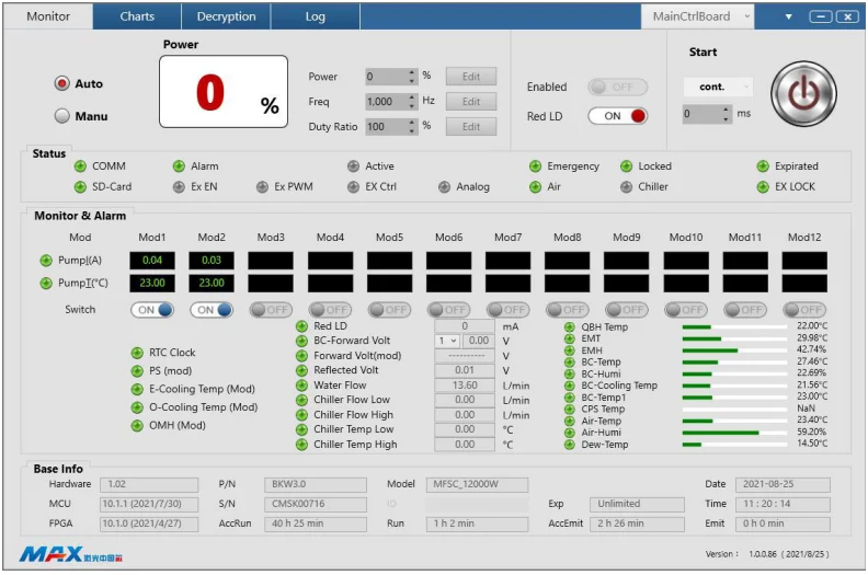
(5) Haga doble clic en el acceso directo del escritorio para abrir la aplicación e ingresar a la siguiente interfaz de conexión.
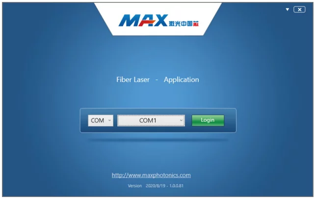
(6) Conecte el láser y la PC con el cable de puerto serial que viene con la conexión aleatoria, seleccione el número de puerto, inicie sesión en el láser e ingrese a la siguiente interfaz de monitoreo. Nota: Al ingresar a la interfaz de monitoreo,
El sistema selecciona el módulo de control externo de forma predeterminada. Modulación externa/habilitación/control de señal DA.
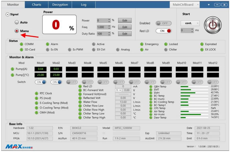
(7) El módulo de control interno controla el láser. (Haga clic para seleccionar el módulo de control interno).
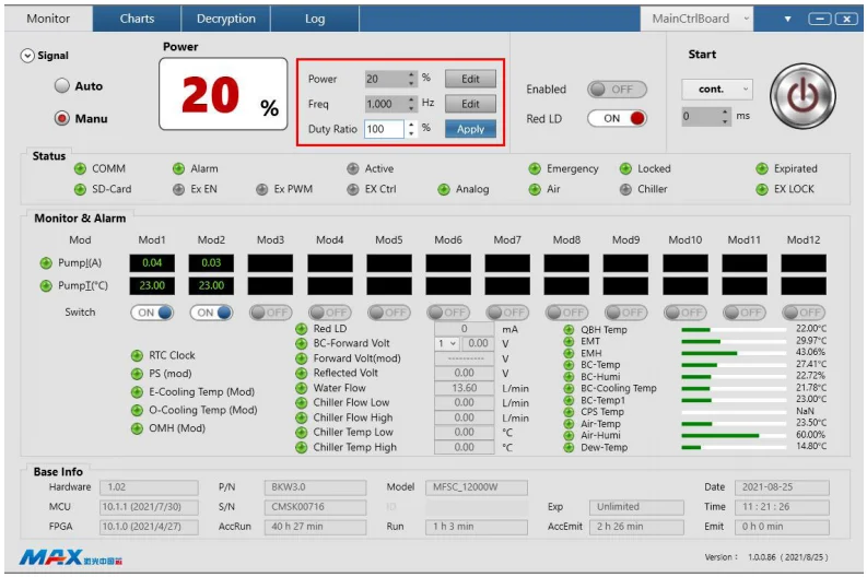
(8) Edite y configure la potencia/frecuencia/ciclo de trabajo del láser.
(9) Haga clic para habilitar la señal de habilitación de la computadora host.
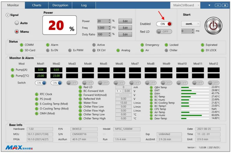
(10) Haga clic para encender el botón de inicio del láser de la computadora superior.
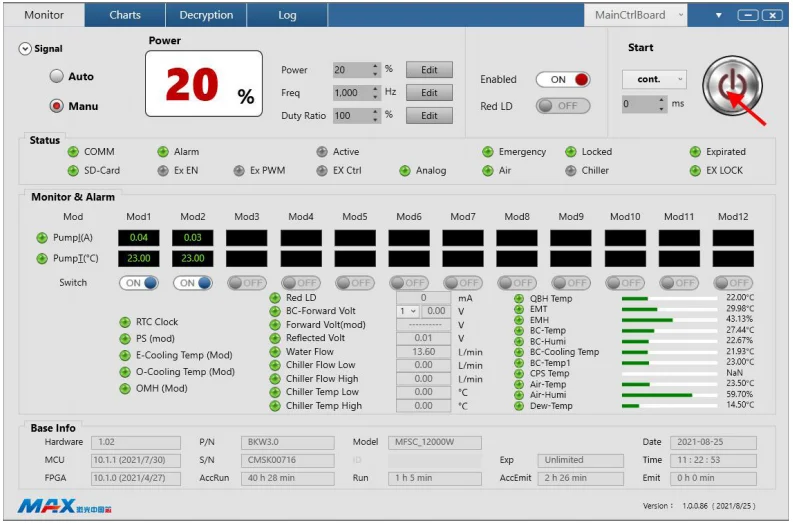
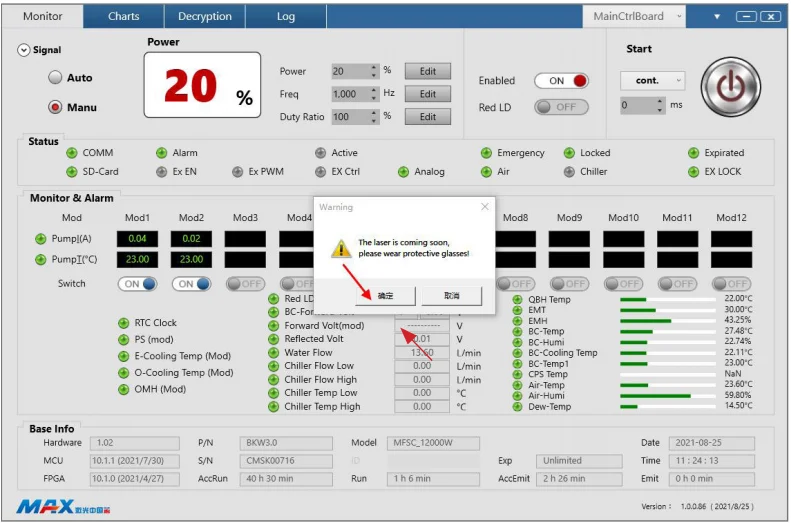
(11) Haga clic en “Sí” en el cuadro de aviso para encender el láser.
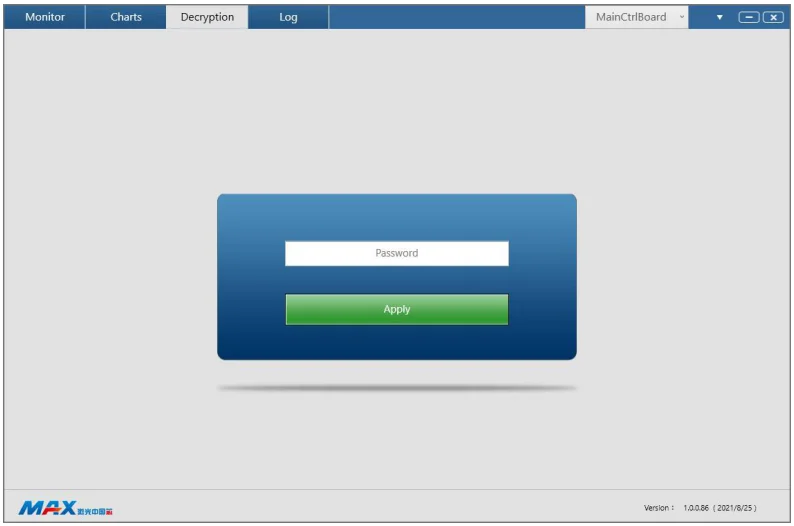
(12) Interfaz de descifrado.
Consejo: Para obtener detalles sobre la instalación del software y las instrucciones de uso, consulte el manual del software en el disco U.
Listado de 7 errores
Los puntos de alarma de falla que establece el láser incluyen:
Alarma de luz delantera PD
Medidas de protección:
Dejó de suministrar energía a la fuente de alimentación principal y apagó el láser.
Posibles causas:
El láser interior no detecta el láser.
Soluciones :
1. Reinicie el láser sin láser y verifique si hay luz roja. Si no hay luz roja, comuníquese con el servicio de atención al cliente de Maxphotonics.
2. Si hay una luz roja, verifique si el módulo correspondiente puede encender el láser. Verifique si la fuente de alimentación de CC y la salida de voltaje del módulo son compatibles.
normal.
Alarma con luz de fondo súper fuerte
Medidas de protección:
Dejó de suministrar energía a la fuente de alimentación principal y apagó el láser.
Posibles causas:
El módulo de combinación de haces detecta que la luz de retorno es demasiado fuerte.
Soluciones:
1. Verifique la posición del enfoque del láser;
2.Verifique que el material esté colocado horizontalmente;
3. Verifique si el material es de ultra alta reflectividad;
4. Verifique que el espesor del material exceda el estándar y no pueda atravesar la alarma;
5. Apague el láser, haga una pausa de 3 a 5 minutos, reinicie el láser y enciéndalo.
Alarma de temperatura de la bomba
Medidas de protección:
Dejó de suministrar energía a la fuente de alimentación principal y apagó el láser.
Posibles causas:
La temperatura de la bomba del módulo láser es demasiado alta, se activa la alarma de temperatura.
Soluciones:
Apague el láser, verifique si el caudal del enfriador de agua y la temperatura del agua son normales y si la tubería de agua está bloqueada.
Después de la inspección, reinicie el láser y el láser volverá a funcionar con normalidad. Si no puede volver a funcionar con normalidad, comuníquese con el servicio de atención al cliente de Maxphotonics.
Alarma de instalación QBH
Medidas de protección:
Dejó de suministrar energía a la fuente de alimentación principal y apagó el láser.
Posibles causas:
El contacto del cabezal de salida QBH tiene mal contacto con el contacto del cabezal de corte.
Soluciones:
Apague el láser, verifique el cabezal de salida del láser QBH y el cabezal de corte, luego vuelva a instalarlo.
Alarma de parada de emergencia
Medidas de protección:
Dejó de suministrar energía a la fuente de alimentación principal y apagó el láser.
Posibles causas El interruptor de parada de emergencia: está presionado.
Soluciones:
Gire la parada de emergencia a normal y reinicie el láser.
Alarma de flujo de agua
Medidas de protección:
Dejó de suministrar energía a la fuente de alimentación principal y apagó el láser.
Posibles causas:
La máquina de enfriamiento de agua es anormal, lo que da como resultado una disminución del flujo de agua.
Soluciones:
Apague el láser, verifique si el caudal del enfriador de agua y la temperatura del agua son normales y si la tubería de agua está bloqueada. Una vez finalizada la inspección, reinicie el láser y volverá a funcionar con normalidad.
Alarma de comunicación anormal
Medidas de protección:
Dejó de suministrar energía a la fuente de alimentación principal y apagó el láser.
Posibles causas:
No hay transmisión de señal entre la línea de comunicación del módulo único y el módulo principal.
Soluciones:
1. Verifique si la línea de señal que conecta el módulo individual y el módulo principal está suelta.
2. Verifique si el módulo individual se puede encender normalmente, si hay luz roja y si la salida de voltaje de la fuente de alimentación auxiliar funciona normalmente.
Alarma de corriente máxima
Medidas de protección:
Dejó de suministrar energía a la fuente de alimentación principal y apagó el láser.
Posibles causas:
La corriente de funcionamiento de la fuente de la bomba del módulo único excede el límite máximo.
Soluciones:
1. Reinicie después de apagar el láser, verifique si es normal; si es normal, úselo normalmente;
2. Si la alarma de corriente máxima continúa sonando, es posible que el tubo MOS de la unidad se averíe en un solo módulo. Debe apagar el láser de inmediato y comunicarse con el servicio de atención al cliente de Maxphotonics.
Alarma de placa de refrigeración por agua del módulo eléctrico
Medidas de protección:
Dejó de suministrar energía a la fuente de alimentación principal y apagó el láser.
Posibles causas:
La temperatura del módulo de agua es demasiado alta y suena la alarma de temperatura.
Soluciones:
Apague el láser, verifique si el caudal del enfriador de agua y la temperatura del agua son normales y si la tubería de agua está bloqueada. Una vez finalizada la inspección, reinicie el láser y volverá a funcionar con normalidad. Si no puede volver a funcionar con normalidad, comuníquese con el servicio de atención al cliente de Maxphotonics.
Alarma de temperatura de la placa de enfriamiento de agua del combinador
Medidas de protección:
Dejó de suministrar energía a la fuente de alimentación principal y apagó el láser.
Posibles causas:
La temperatura del módulo de agua es demasiado alta y suena la alarma de temperatura.
Soluciones:
Apague el láser, verifique si el caudal del enfriador de agua y la temperatura del agua son normales y si la tubería de agua está bloqueada. Una vez finalizada la inspección, reinicie el láser y este volverá a funcionar con normalidad. Si no puede volver a funcionar con normalidad, comuníquese con el servicio de atención al cliente de Maxphotonics.
NOTA:
◎ Toda la información de alarma láser se mostrará en el software de monitoreo con el recordatorio correspondiente: ¡preste atención! Si tiene alguna pregunta, comuníquese con nuestro personal de atención al cliente.
Capítulo 6: Servicio y mantenimiento
1-Instrucciones de mantenimiento
Antes de conectar el conector de fibra óptica láser, es necesario comprobar la presencia de polvo, suciedad y daños en la cara final. El uso de conectores de fibra óptica sucios o no limpios puede provocar graves daños al láser. Maxphotonics no se hace responsable de los daños al láser causados por el uso de conectores de fibra óptica no limpios. Si el conector de fibra óptica se manipula de forma privada, el equipo perderá su garantía.
Para limpiar un conector de fibra necesitas los siguientes materiales:
1. Guantes de goma sin polvo o dedil;
2. Toallitas y/o hisopos de limpieza óptica sin pelusa;
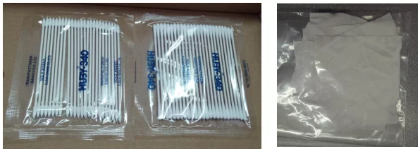
3. Etanol anhidro (nivel óptico, pureza >99,5%);
4.Aire comprimido (sin aceite, sin agua), o una varilla de madera enrollada con una cinta adhesiva de doble capa;
5. Microscopio de escala (se puede ampliar hasta 20 veces o más).

IMPORTANTE:
◎ Es imprescindible que utilice guantes de goma sin polvo durante este procedimiento de limpieza. Se advierte que el conector de fibra puede sufrir daños debido a una manipulación incorrecta, al uso de procedimientos de limpieza incorrectos o a la utilización de productos químicos para la limpieza. Esto no está cubierto por la garantía de Maxphotonics.
2-Inspección de apariencia
1. Requisitos medioambientales
La limpieza y la instalación del cabezal de corte LOE se deben realizar en el banco de trabajo de purificación de la sala limpia, el grado libre de polvo requiere 1000 grados y el banco de trabajo de limpieza de referencia es el siguiente:
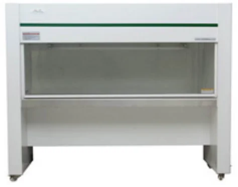
2. Procedimientos operativos
1. Apague el láser y coloque el interruptor de llave en la posición "OFF";
2. Gire la funda protectora negra del conector en el sentido de las agujas del reloj, colóquela bajo un microscopio de 20 aumentos y limpie la superficie a inspeccionar, y verifique si la apariencia de la varilla de cuarzo cumple con el estándar de apariencia. (referencia 2.2.5);
3. Si no hay partículas de polvo, o las partículas de polvo cumplen con los estándares de apariencia, coloque la funda protectora negra para devolver el conector;
4. Si se encuentra que las partículas de polvo exceden los requisitos estándar de apariencia, límpielas de acuerdo con los requisitos del paso 3;
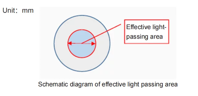
5. Los estándares de apariencia se muestran en la siguiente tabla:
| Fuerza | Varilla de cuarzo | |
| Área efectiva de paso de luz (dentro de φ3 mm) | Área de paso de luz no efectiva (exterior φ3mm) | |
| 4000W-30KW | Diámetro de picadura: No permitido Ancho del rayado: No permitido | Diámetro de picadura: ≤ 0,1 Ancho del rayado: ≤ 0,005 |
| 2000W-4000W | Diámetro de picadura: ≤ 0,05 Ancho del rayado: ≤ 0,002 | Diámetro de picadura: ≤ 0,1 Ancho del rayado: ≤ 0,005 |
| Por debajo de 2000W (Módulo único | Diámetro de picadura: ≤ 0,1 Ancho del rayado: ≤ 0,005 | Diámetro de picadura: ≤ 0,1 Ancho del rayado: ≤ 0,01 |
3-Procedimientos de limpieza
1. Apague el láser y coloque el interruptor de llave en la posición "OFF"
2.Limpieza de la lente protectora con hisopos
1. Gire la funda protectora negra del conector en el sentido de las agujas del reloj, coloque la superficie interior o exterior bajo un microscopio 20 veces y límpiela. Después de una observación cuidadosa, determine la posición específica de las partículas de polvo, abra la tapa de la botella de alcohol y presione suavemente la boca de la botella de alcohol para que salga una pequeña cantidad de alcohol, sumerja completamente el hisopo de algodón redondo en alcohol y luego frote suavemente el hisopo de algodón para eliminar el exceso de alcohol. Utilice un hisopo de algodón para limpiar las partículas de polvo en línea recta en la dirección del cuerpo del operador.
La fuerza debe ser leve. Después de cada pasada, el hisopo de algodón se puede girar 180° y luego pasar el otro lado. Después de pasar el hisopo dos veces, se raspa. Tenga en cuenta que no se permite hacer círculos ni pasar el hisopo de un lado a otro para evitar que las partículas de polvo contaminen otras áreas o que los hisopos de algodón rayen directamente la superficie. Después de toda la limpieza, es necesario observar nuevamente bajo el microscopio si la superficie está limpia.
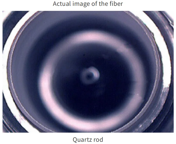
La cara final puede estar dañada
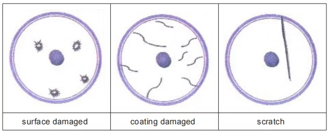
2. Compruebe con el microscopio si hay cuerpos extraños visibles en la pared interior del tubo guía protector. Si los cuerpos extraños se pueden limpiar con una barra de pegamento de doble cara, utilice un hisopo de algodón para limpiar el alcohol y continuar con la limpieza.
Después de que el tubo guía protector se haya secado, colóquelo directamente en el conector.
3. Método de limpieza para varillas de cuarzo.
Si descubre que la varilla de cuarzo interna está sucia o llena de polvo, puede abrir la lente para limpiarla. Los pasos específicos son los siguientes:
1. Gire la funda protectora negra, la tapa antipolvo y la lente protectora en el sentido de las agujas del reloj, primero limpie la circunferencia y la superficie de la rosca de toda la pieza de la lente del conector con un paño de limpieza óptica y alcohol;

2. Coloque la varilla de cuarzo bajo un microscopio de 20 aumentos y límpiela. Después de una observación cuidadosa, determine la ubicación específica de las partículas de polvo y límpielas de acuerdo con el método del apartado 3.2.1. Para las partículas de polvo en el costado de la varilla de cuarzo fundido, use un hisopo de algodón puntiagudo para limpiar a lo largo de la superficie circunferencial.
Después de toda la limpieza, confirme bajo el microscopio si está limpio, incluida la zona biselada. Por último, envuélvalo sobre la mesa con una tela no tejida y luego continúe con el resto del trabajo para evitar que el polvo contamine nuevamente la cara final y los lados de la varilla de sílice fundida;
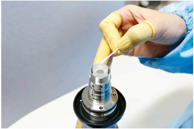
3. Siguiendo la dirección de la veta de la superficie de la pieza metálica, gire suavemente la pieza de la lente hacia la pieza metálica y confirme que esté en su lugar. Coloque la funda protectora negra en el conector.

IMPORTANTE:
◎ No reutilice una toallita o hisopo óptico sin pelusa;
◎ No toque la lente protectora del conector de fibra;
◎ No sople directamente, de lo contrario se generará nueva suciedad;
◎ No toque la punta del hisopo de limpieza con los dedos;
◎ Es necesario realizar una limpieza antes de colocar la cubierta protectora y la funda;
◎ Nunca sople aire directamente a la superficie, ya que podría incrustarse.
contaminantes en la superficie. Siempre sople sobre la superficie;
◎ Si el conector de fibra no se puede instalar en el sistema óptico inmediatamente, cúbralo con la tapa protectora limpiada con aire comprimido;
◎ Asegúrese de operar en un entorno limpio de clase 1000
Instalación y precauciones del cabezal de corte 4-LOE
1. Pasos de instalación
1. El cabezal hembra LOE se fija al cabezal de corte y se gira en el sentido de las agujas del reloj hasta la posición fija;
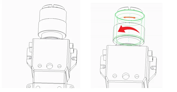
2. Inserte el macho LOE limpio en la posición de ranura fija hembra correspondiente.
Para evitar la contaminación por polvo en la cara del extremo LOE y el interior del cabezal de corte, asegúrese de que el LOE y el cabezal de corte estén en estado horizontal;
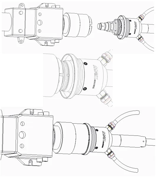
3.Gire el conector macho en el sentido de las agujas del reloj hasta una posición fija.
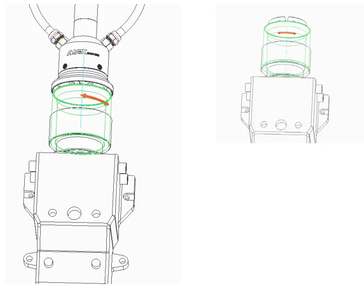
2.IMPORTANTE
◎ La lente del cabezal macho LOE debe retirarse antes de insertar el cabezal hembra;
◎ Después de retirar la lente, es necesario limpiar la varilla de cuarzo y la rosca del miembro de la lente fija;
◎ La cabeza hembra del inserto macho LOE debe estar centrada para evitar dañar la varilla de cuarzo;
◎ Todo el proceso operativo debe realizarse en un entorno de purificación libre de polvo de nivel 100.
Capítulo 7: Guía de desmontaje
1-Pasos para desembalaje
El láser pertenece a los objetos de valor precisos, por lo que Maxphotonics recomienda los siguientes pasos para desembalar la caja. La lista de embalaje se adjunta a la caja.
Después de desembalar, verifique los accesorios de acuerdo con la lista de embalaje.
Guarde también todos los artículos después de desembalarlos para evitar su transporte o almacenamiento en el futuro.
La siguiente imagen muestra los pasos para retirar la caja:
1. Coloque la caja que contiene el equipo láser en un lugar estable, como un piso plano o una plataforma grande.
2. Le recomendamos que utilice un destornillador de punta gruesa para hacer palanca en el clip de plástico, quitar el broche de plástico y luego quitar la cubierta superior.
3. Levante la viga superior y retírela, teniendo cuidado de no rayar el cable superior.
4. Retire la espuma superior y recoja el accesorio.
5. Siga el segundo paso para quitar los cuatro paneles laterales, en el orden de bordes largos -> lados cortos -> otro lado corto -> otro lado largo.
6. Retire la correa tensora y la bolsa de PE, preste atención a la dirección de ajuste del trinquete y al método de apertura de la correa:
- Mantenga presionado el anillo de retención de tope
- Girando y tensando la horca 180°
- Tire de las correas con fuerza
7. Utilice una carretilla elevadora o una grúa para levantar el láser y moverlo a la posición designada.
Cuando los clientes necesiten reembalar, consulte los siguientes pasos.
1. Coloque el pallet y límpielo, luego coloque la correa tensora y pase la correa tensora por las ranuras inferiores en ambos lados del pallet.
2. Utilice una carretilla elevadora para llevar el producto a una determinada altura, mueva el palé hasta el fondo y coloque el producto lentamente. Al colocar el producto, preste atención a la dirección del producto como se muestra.
3. Coloque la bolsa de PE, apriete la correa tensora y separe las esquinas de papel entre el producto y la correa tensora. Hay 4 esquinas de papel. Preste atención al uso de la banda tensora:
- Localice la posición del eje de la ranura y pase la correa desde debajo del eje de la ranura;
- Apriete la correa y gírela nuevamente a la posición del eje de la ranura;
- Las correas están desgastadas y
- Apretó las correas;
- Agite el mango hacia adelante y hacia atrás para
4. Ensamble el panel lateral, inserte la hebilla de plástico en la ranura y ajústela. La secuencia de ensamblaje es: lado largo -> lado corto -> otro lado corto -> otro lado largo.
5. Ensamble el soporte superior y la espuma superior, teniendo cuidado que el soporte superior sea para colgar los paneles laterales.
6. Ensamble la cubierta superior y abroche todas las hebillas de plástico.
NOTA:
◎ Si encuentra algún daño en el embalaje exterior o en los componentes internos después de recibir el producto, comuníquese con Maxphotonics o con su representante local de inmediato.
◎ El láser está equipado con un deshumidificador. Cuando la temperatura y la humedad ambiente son demasiado altas, el láser tendrá un proceso para evitar la condensación y la deshumidificación (aproximadamente 30 minutos). El agua condensada saldrá por la salida inferior del gabinete.
◎ Cuando se apaga el láser, también se debe apagar el enfriador de agua para evitar que se produzca condensación debido a una diferencia excesiva de temperatura.
RECOMENDACIÓN:
Cambie la temperatura de funcionamiento o la humedad del láser para mantenerlo alejado del punto de rocío (por ejemplo, instalando el láser en una habitación con aire acondicionado).
| No. | Nombres de los accesorios | Descripción | Unidad | Cantidad |
| 1 | Láser de fibra óptica | MFSC-XXX | Ordenador personal | 1 |
| 2 | Cable serial USB a RS232 | BLT | 1 | |
| 3 | Cable | BLT | 1 | |
| 4 | Llave | Ordenador personal | 2 | |
| 5 | Disco U | Ordenador personal | 1 | |
| 6 | Abrazadera | Ordenador personal | 2 | |
| 7 | RS232 (externo) | BLT | 1 | |
| 8 | Cable adaptador de control externo del cliente | BLT | 1 | |
| 9 | Línea de control externa | BLT | 1 | |
| 10 | Interfaz de control externo continuo Junta de seguros PCBA | Ordenador personal | 1 | |
| 11 | Paño antipolvo superfino (2x2) | Ordenador personal | 6 | |
| 12 | Tubo de muestra de tubería de agua QBH | BLT | 1 | |
| 13 | Tubo de muestra de tubería de agua con láser | BLT | 1 | |
| 14 | Hisopo de algodón puntiagudo | Bolsa | 1 | |
| 15 | Hisopo de algodón con punta redonda | Bolsa | 1 |
Capítulo 8: Servicio y mantenimiento
1-Notas de mantenimiento
PRECAUCIÓN :
◎ No hay piezas que el operador pueda reparar en el interior. Solicite cualquier servicio técnico a personal calificado de Maxphotonics.
◎ Para garantizar que se puedan llevar a cabo las reparaciones o el reemplazo dentro del alcance de la garantía y que se mantengan perfectamente sus intereses, envíe una solicitud a Maxphotonics o al representante local después de encontrar las fallas. Una vez que reciba nuestra autorización, debe empaquetar el producto en un paquete adecuado y devolverlo.
◎ Debe conservar la prueba en caso de encontrar algún daño después de recibir el producto, para poder reclamar los derechos a los transportistas.
IMPORTANTE :
◎ No envíe ningún producto a Maxphotonics sin autorización de devolución de material (RMA), de lo contrario, se devolverá por rechazo. Las pérdidas resultantes correrán a cargo del cliente; para garantizar el procesamiento oportuno de la devolución de la máquina, el cliente debe enviar la máquina defectuosa a la dirección designada de Maxphotonics.
Si el producto está más allá del período de garantía o del alcance de la garantía, los clientes serán responsables del costo de reparación. Los cargos específicos incluyen costos de repuestos, tarifas de servicio de mano de obra y viajes, alojamiento y otros gastos incurridos por los servicios en el sitio.
CAMBIAR :
◎ Tenemos el derecho de cambiar cualquier diseño o estructura de nuestro producto, y la información está sujeta a cambios sin previo aviso.
2-Declaraciones de servicios
Si tiene más problemas relacionados con la seguridad, la instalación, el funcionamiento o el mantenimiento, lea atentamente esta “Guía del usuario” y siga estrictamente los pasos de funcionamiento. Llame al Departamento de atención al cliente si tiene otras preguntas.


