Спасибо за использованиее Руководство по эксплуатации источника волоконного лазера мощностью 40000 Вт. Мы составляем этот документ для вас, чтобы лазер использовался и обслуживался надлежащим образом.
Пожалуйста, уделите время чтению и пониманию этого Руководства пользователя и ознакомьтесь с инструкциями по эксплуатации и обслуживанию перед использованием продукта. Мы настоятельно рекомендуем оператору прочитать Раздел 2 под названием «Информация по безопасности» перед эксплуатацией продукта.
Данное руководство пользователя должно оставаться вместе с изделием, чтобы предоставить вам и всем будущим пользователям и владельцам изделия важную информацию по эксплуатации, технике безопасности и другую информацию.
Мы подчеркиваем те части документа, на которые вам следует обратить особое внимание. Пожалуйста, обратите внимание на эту информацию, чтобы предотвратить ненужные повреждения.
Оглавление
Глава 1: Характерное описание
Серия MFMC CW Волоконный лазер Изделия обеспечивают широкий диапазон длин волн от 1060 нм до 1100 нм. Лазеры имеют водяное охлаждение, не требуют технического обслуживания, имеют КПД более 30% и обеспечивают высокую эффективность, надежность и производительность.
Серия волоконных лазеров Maxphotonics MFMC Series CW — это лазерные продукты класса 4, разработанные и испытанные с соблюдением требований безопасности. При соблюдении данного руководства пользователя и применении надежных методов лазерной безопасности устройство будет безопасным и надежным.
Лазерный свет обладает уникальными характеристиками, которые могут представлять опасность. Поэтому лазерный свет обычно не может ассоциироваться с другими источниками света, и все операторы и люди, находящиеся вблизи лазера, должны знать об этих особых опасностях.
Для обеспечения безопасной эксплуатации и оптимальной производительности изделия соблюдайте все предупреждения и инструкции по технике безопасности, содержащиеся в настоящем руководстве, в процессе эксплуатации, технического обслуживания и ремонта и не разбирайте устройство.
Нет обслуживаемых деталей, оборудования или узлов, связанных с этим продуктом для пользователя. Лазеры несанкционированной разборки не подлежат гарантии.

Глава 2: Общая информация по безопасности
1-Конвенции по безопасности
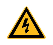
ПРЕДУПРЕЖДЕНИЕ: Относится к потенциальной опасности поражения электрическим током для человеческого тела. Требует процедуры, которая, если ее не выполнить правильно, может привести к телесным повреждениям для вас и/или других.
Не продолжайте движение дальше знака ПРЕДУПРЕЖДЕНИЕ, пока полностью не поймете и не выполните требуемые условия.

ВНИМАНИЕ:Относится к потенциальной опасности на продукте. Требует процедуры, которая, если ее не соблюдать правильно, может привести к повреждению продукта или компонентов. Чтобы обеспечить нормальное использование оборудования, не нарушайте требования знака ВНИМАНИЕ.
ПРИМЕЧАНИЕ :
◎ Это устройство классифицируется как лазерный инструмент высокой мощности класса IV. Он может излучать до 3000 Вт средней мощности в диапазоне от 1060 нм до 1100 нм. Этот уровень света может вызвать повреждение глаз и кожи. Несмотря на то, что излучение невидимо, луч может вызвать необратимое повреждение сетчатки. Защитные очки от лазера не поставляются с этим прибором, но их необходимо носить все время, пока лазер работает.
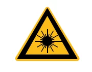
ПРЕДУПРЕЖДЕНИЕ: Относится к потенциальной опасности лазера. Символ представляет лазерное излучение. Символ наклеен на выходной конец лазера.
НЕТ СИМВОЛА
ВАЖНО:Относится к любой информации, касающейся работы продукта. Пожалуйста, не упускайте эту информацию из виду.
ПРИМЕЧАНИЕ :
◎ Это устройство классифицируется как лазерный инструмент высокой мощности класса IV. Он может излучать до 40/50 кВт средней мощности от 1060 нм до 1100 нм. Этот уровень света может вызвать повреждение глаз и кожи. Защитные очки от лазера не поставляются с этим прибором, но их необходимо носить все время, пока лазер работает.
При работе с данным устройством используйте соответствующие защитные очки от лазерного излучения.
2-Защита от лазерного излучения
1.Требования к защите от лазерного излучения
Вы должны носить защитные очки при работе с лазером и рационально выбирать защитные очки в соответствии с длиной волны лазерного излучения. Если устройство представляет собой настраиваемый лазер или продукт Рамана, оно излучает свет в диапазоне длин волн, и конечный пользователь должен убедиться, что используемые защитные очки для лазерной защиты защищают от света, излучаемого устройством во всем диапазоне длин волн.
2.Поставщики средств защиты от лазерного излучения
Maxphotonics рекомендует вам материалы или оборудование, предоставленные следующими поставщиками средств лазерной защиты, включая LaserVision USA, Kentek Corporation, Rochwell Laser Industries и т. д. Вся информация о поставщиках предоставляется Maxphotonics исключительно для удобства использования, поэтому Maxphotonics не несет ответственности за любые проблемы, вызванные использованием продукции вышеупомянутых поставщиков.
3-Стандартный эталон
Электромагнитная совместимость Излучение:
EN МЭК 61000-6-4:2019
СИСПР 16-2-1
СИСПР 16-2-3
Характеристики помехоустойчивости по электромагнитной совместимости:
EN МЭК 61000-6-2:2019
EN 61000-4-2:2009
EN 61000-4-3:2020
EN 61000-4-4:2012
EN 61000-4-5:2014+A1:2017
EN 61000-4-6:2014
EN 61000-4-11:2020
Лазерная безопасность:
EN 60825-1:2014+A11:2021
CDRH 21 CFR 1040.10
Безопасность электрической системы:
EN 60204-1:2018
ПРИМЕЧАНИЕ:
◎ Характеристики лазера Maxphotonics MFMC соответствуют требованиям сертификации CE EMC, требованиям EMC, указанным в "Директиве EMC" европейского рынка. Соответствуют стандарту "EMC" EN 61000-6-4 по излучению и требованиям по защите от помех EN 61000-6-2.
◎ В соответствии с соответствующими национальными стандартами и требованиями лазер должен быть классифицирован в соответствии с его выходной мощностью и длиной волны лазера. Все лазерные изделия серии MFMC с высокой мощностью относятся к изделиям Класса 4 (согласно разделу J,1040.10 (d) Части Ⅱ, 21 CFR).
◎ Согласно стандартам ЕС, оборудование относится к приборам 4 класса (согласно статье 9, EN 60825-1).
4-Общие инструкции по технике безопасности
1. Зеркальное отражение
Часто в выходном порту лазера под разными углами генерируется множество вторичных лазерных лучей. Эти расходящиеся лучи возникают, когда первичный луч лазера отражается от гладкой поверхности, и их называют зеркальными отражениями. Хотя эти вторичные лучи могут быть менее мощными, чем общая мощность, излучаемая первичным лучом, их интенсивность может быть достаточно большой, чтобы вызвать повреждение глаз и кожи, а также поверхности материалов.
ПРЕДУПРЕЖДЕНИЕ:
◎ Необходимо проявлять осторожность, чтобы избежать/свести к минимуму зеркальные отражения, поскольку лазерное излучение невидимо!
2.Инструкции по технике безопасности при использовании аксессуаров
Фоточувствительные элементы, встроенные в оптические аксессуары, связанные с лазером, могут быть повреждены лазерным излучением, например: видеокамеры, фотоумножители и фотодиоды. Следует обратить внимание на защиту соответствующих устройств.
ПРЕДУПРЕЖДЕНИЕ :
◎ Лазерный свет Maxphotonics MFMC достаточно силен, чтобы резать или сваривать металл, прожигать кожу, одежду и краску. Кроме того, этот свет может воспламенить летучие вещества, такие как спирт, бензин, эфир и другие растворители. Во время рабочего процесса горючие материалы вокруг лазера должны быть изолированы.
3.Инструкции по эксплуатации оптического прибора
Мы настоятельно рекомендуем вам прочитать следующие процедуры перед эксплуатацией лазера:
1. Никогда не смотрите прямо в выходной порт лазера, когда питание включено.
2. Избегайте расположения лазера и всех оптических выходных компонентов на уровне глаз.
3. Оснащен кожухом лазерного луча.
4. Перед включением лазера обязательно снимите заднюю крышку выходной головки лазера, в противном случае это приведет к необратимому повреждению выходного волокна лазера.
голова.
5. Убедитесь, что все средства индивидуальной защиты соответствуют выходной мощности и диапазону длин волн лазера.
6.Используйте лазер в помещении, доступ в которое контролируется дверными замками. Разместите предупреждающие знаки. Ограничьте безопасные зоны для работы с лазером.
7. Пожалуйста, не используйте лазер в затемненных помещениях.
8. Не включайте лазер без оптоволоконного соединителя или оптического выходного разъема.
9. Выполните ввод в эксплуатацию, калибровку и фокусировку при низкой выходной мощности, а затем постепенно увеличивайте выходную мощность после завершения калибровки и фокусировки.
10. Не устанавливайте и не снимайте режущие головки или коллиматоры, когда лазер включен.
11. Перед установкой или снятием режущих головок или коллиматоров убедитесь, что лазер выключен и питание отключено.
12. Если оборудование эксплуатируется способом, не указанным в настоящем документе, защитные устройства и производительность оборудования могут быть нарушены, а гарантия будет аннулирована.
ОСТОРОЖНОСТЬ:
◎ Выход лазера осуществляется через линзу с антибликовым покрытием. Если на пути света обратного каскада вашего лазера имеется оптическая линза, пожалуйста, тщательно осмотрите линзу выходной головки и линзу обратного каскада лазера и убедитесь, что на линзе нет пыли и других загрязнений.
Обратите внимание, что любое макроскопическое наложение может привести к серьезному повреждению линзы или сжечь лазер или любое оборудование на обратном пути светового потока.
◎ Инструкции по очистке линз см. в «Руководстве по проверке и очистке оптоволоконных разъемов».
◎ При работе лазера могут образовываться горячие или расплавленные куски металла. Соблюдайте осторожность, если во время работы образуются обломки.
◎ При выполнении пусконаладочных работ и калибровки выходной мощности лазера необходимо установить выходную мощность лазера на низкий уровень, а затем постепенно увеличивать выходную мощность, проверяя качество светового пятна, излучаемого лазером, с помощью инфракрасного визора.
ПРЕДУПРЕЖДЕНИЕ:
◎ Убедитесь, что средства индивидуальной защиты соответствуют выходной мощности и диапазону длин волн лазера.
◎ Никогда не смотрите прямо в оптическое волокно или коллиматор и обязательно надевайте защитные очки при каждой операции.
4.Инструкции по эксплуатации электрооборудования
Мы настоятельно рекомендуем вам прочитать следующие процедуры перед эксплуатацией лазера:
1. Напряжение питания лазерного оборудования - трехфазный переменный ток 360-440 В переменного тока, 3P+PE. Лазерное оборудование должно быть надлежащим образом заземлено во время установки и монтажа. Внешние кабели шкафа должны быть размещены в металлических коробах или металлических трубах во время установки. Обратите внимание на безопасность электричества во время использования, чтобы предотвратить поражение электрическим током.
2. При разборке лазера сначала отключите питание. Если произошло поражение электрическим током, следует принять корректирующие меры для предотвращения вторичного поражения. Правильный процесс лечения: отключите питание, безопасно освободите персонал, вызовите помощь и сопроводите пострадавшего.
3. Оборудование не имеет частей, которые могут обслуживаться операторами, и все операции по техническому обслуживанию должны выполняться специалистами Maxphotonics.
4.Во избежание поражения электрическим током не снимайте корпус, не отсоединяйте лазер без разрешения и не повреждайте соответствующие знаки. Любое изделие с несанкционированным демонтажем не подлежит гарантии.
ПРЕДУПРЕЖДЕНИЕ:
◎ Входное напряжение лазера — трехфазный переменный ток (360-440 В переменного тока, 3P+3E), что может вызвать риск поражения электрическим током. Все соответствующие кабели и соединительные провода несут потенциальную опасность.
5. Условия окружающей среды и меры предосторожности
Для обеспечения безопасности рабочей зоны лазера должны быть применены соответствующие ограждения, включая, помимо прочего, знаки безопасности лазера и блокировочные устройства. Соответствующие операторы должны быть обучены и проверены и знать обычные требования безопасности для работы с лазером. Между тем, важно, чтобы выходные компоненты не были установлены на уровне глаз.
Из-за взаимодействия лазера и металлического материала может возникнуть излучение ультрафиолетового света высокой интенсивности или видимого света. Убедитесь, что лазер снабжен защитным кожухом, чтобы предотвратить повреждение глаз или других частей тела человека излучением.
Мы рекомендуем вам соблюдать следующие эксплуатационные меры продлить срок службы лазера:
1.Для обеспечения хороших условий эксплуатации лазера, снижения риска образования конденсата, снижения вероятности выхода из строя и продления срока службы.
Настоятельно рекомендуется заранее сконфигурировать кондиционируемое помещение лазера. Кондиционируемое помещение должно быть достаточно просторным, чтобы облегчить внутреннее обслуживание. Оно может гарантировать минимальное свободное пространство вокруг лазера в 1,0 м. Если пространство ограничено, кондиционируемое помещение должно быть спроектировано так, чтобы его можно было легко демонтировать и установить.
2.Необходимо обеспечить достаточное пространство для установки охладителя с воздушным охлаждением и обеспечить достаточный выхлоп охладителя с водяным охлаждением. Минимальное свободное пространство сверху вентилятора с воздушным охлаждением составляет 1,5 м, а боковая пластина воздушного фильтра находится на расстоянии 1 м от стены.
3. Запрещается размещать машину с воздушным охлаждением и водяным охлаждением в помещении с лазерным кондиционером. Поскольку машина с воздушным охлаждением и водяным охлаждением выбрасывает много горячего воздуха, температура в помещении быстро повышается, и в конечном итоге рассеивание тепла становится плохим, что приводит к срабатыванию сигнализации высокого давления машины с водяным охлаждением и сигнализации конденсации лазера.
4. Не подвергайте лазер воздействию повышенной влажности.
5. Устройство оснащено охлаждающими вентиляторами. Убедитесь, что поток воздуха достаточен для охлаждения лазера, любые предметы или мусор, закрывающие вентиляционные отверстия, должны быть всегда удалены.
6. Эксплуатация при более высокой температуре ускорит старение, увеличит пороговый ток и снизит эффективность спада. Если устройство перегрелось, прекратите работу и свяжитесь с Maxphotonics.
7.Убедитесь, что рабочая поверхность хорошо проветривается. При взаимодействии лазера с рабочей поверхностью могут образовываться газы, искры и мусор, и они могут представлять дополнительную опасность.
ОСТОРОЖНОСТЬ :
◎ Устройство может быть повреждено при неосторожном использовании.
5-Дополнительная информация по безопасности
Дополнительную информацию о безопасности лазерного излучения см. в списке ниже:
Американский институт лазеров (LIA)
13501 Ingenuity Drive, офис 128
Орландо, Флорида 32826
Телефон: 407 380 1553, Факс: 407 380 5588
Бесплатный номер: 1 800 34 ЛАЗЕР
Американский национальный институт стандартов
ANSI Z136.1, Американский национальный стандарт безопасного использования лазеров
(Доступно через LIA)
Международная электротехническая комиссия
МЭК 60825-1, издание 1.2
Центр приборов и радиологического здоровья
21 CFR 1040.10 — Стандарты производительности для светоизлучающих изделий
Министерство труда США - OSHA
Публикация 8-1.7 — Руководство по безопасности и оценке опасности лазеров.
Оборудование для лазерной безопасности
Издательство Лорин
Оборудование для лазерной безопасности и руководства для покупателей
Глава 3: Описание продукта
1-Особенности
Волоконные лазеры серии MFSC CW — это компактные и эффективные лазеры с высококачественным выходом лазерного излучения, разработанные для промышленного применения. Они в основном применяются в областях штамповки, сварки, резки и т. д.
Основные характеристики:
1. Высококачественный лазерный выход
2. Высокая мощность, высокая эффективность
3. Высокая надежность, длительный срок службы.
4. Компактный, прочный корпус.
5. Интерфейс расширенного программирования
Приложения:
1. Промышленное применение
2. Научные исследования
Конфигурация из 2 модулей
Maxphotonics предлагает множество настраиваемых режимов. Это руководство даст полные инструкции для всех режимов, см. раздел 6.3-6.6.
Коды обозначения моделей 3-лазера
| М – Ж – С – К – XXX – XX 1 – 2 – 3 – 4 – 5 – 6 | ||
| 1 | Код производителя | M означает Maxphotonics |
| 2 | Средства массовой информации усиления лазер | F означает волоконный лазер |
| 3 | Режим лазера | S означает одномодовый |
| 4 | Лазерное состояние | C означает продолжить волну |
| 5 | Максимальная производительность власть | XXXX Вт означает максимальную выходную мощность лазер |
| 6 | Дополнительное сообщение | Может быть нулевым |
4–Сертификация
Maxphotonics подтверждает, что данное оборудование было тщательно протестировано и проверено и соответствует опубликованным спецификациям перед отправкой. Получив оборудование, проверьте, не были ли повреждены упаковка и принадлежности при транспортировке. Если повреждения очевидны, немедленно свяжитесь с Maxphotonics.
5- Описание передней панели
| Предметы | Описание функции |
| ① ГЛАВНЫЙ ВЫКЛЮЧАТЕЛЬ | Главный выключатель питания лазера 440 В переменного тока |
| ② ПЕРЕКЛЮЧАТЕЛЬ С КЛЮЧОМ | Выключатель питания лазера |
| ③ АВАРИЙНАЯ ОСТАНОВКА | Аварийная остановка |
| ④ СТАРТ | Запустить лазер (сигнал включения-выключения аппаратное обеспечение) |
| ⑤ ТРЕВОГА | Ненормальная ситуация свет лазер |
| ⑥ АКТИВНЫЙ | Нормальная ситуация свет лазер |
| ⑦ МОЩНОСТЬ | Мощность света лазера |

6-Описание задней панели
| Предметы | Описание функции |
| ① CTRL | Внешний разъем управления |
| ②ETHERNET | Сетевой интерфейс связи |
| ③ВЫХОД ВОДЫ | Выходной порт водяного охлаждения (40 кВт и 50 кВт 2 дюйма) |
| ④ВОДА ВНУТРИ | Входной порт водяного охлаждения (40 кВт и 50 кВт 2 дюйма) |
| ⑤ AC380В | Вход переменного тока 360-440 В переменного тока |

7-Оптический выходной терминал
1.Оптическая выходная головка
Оптоволоконная головка используется в соответствии с защитным окном и может быть заменена после повреждения. Перед использованием обязательно снимите черную торцевую крышку с головки LOE, которая обычно устанавливается вместе с лазером. Обратитесь к Главе 6 «Руководство по осмотру и очистке оптоволоконных разъемов» для получения информации о чистящих средствах и методах для защитного окна.
Оптическая выходная головка (LOE-P、LOE-T) MFMC-40000

Оптическая выходная головка (LOE-S) MFMC-50000

Глава 4: Спецификация
1-Параметры оптических характеристик
| Характеристики | Условия испытания | Мин. | Номинал. | Макс | Единица |
| Операционный модуль | CW/Модулированный | ||||
| Поляризация | Случайный | ||||
| МФМК-40000 | Выходная мощность CW 100% | 40000 | Вт | ||
| МФМК-50000 | Выходная мощность CW 100% | 50000 | Вт | ||
| Диапазон настройки выходной мощности | 10 | 100 | % | ||
| Длина волны излучения | 100% CW | 1070 | 1080 | 1090 | нм |
| Ширина спектра (3 дБ) | 100% CW | 5 | 8 | нм | |
| Краткосрочная мощность нестабильность | 100% CW >1ч | ±1 | ±2 | % | |
| Долгосрочная мощность нестабильность | 100% CW >24ч | ±2 | ±3 | % | |
| Качество луча (BPP) | Выходной сердечник волокна диаметр 100мкм | 4 | 5.5 | мм х мрад | |
| Выходной сердечник волокна диаметр 150мкм | 5.5 | 6.5 | |||
| Выходной сердечник волокна диаметр 200мкм | 8 | 10 | |||
| Время включения лазера | 150 | 200 | мкс | ||
| Время выключения лазера | 150 | 200 | мкс | ||
| Скорость модуляции | 100% Выход | 5 | КГц | ||
| Мощность красного направляющего лазера | 400 | uW | |||
| Длина питающего оптоволоконного кабеля | 20 | м | |||
| Размер сердцевины питающего волокна | 150 (100/200 можно настроить) | ||||
| Подача оптоволоконного кабеля радиус изгиба | 200 | ||||
| Форма вывода | ЛОЭ | ||||
2-Общие характерные параметры
| Характеристики | Условия испытания | Мин. | Номинал. | Макс | Единица |
| Рабочее напряжение | 360 | 400 | 440 | ВАК | |
| Входная мощность | MFMC-40000 100% выход | 132 | кВт | ||
| MFMC-50000 100% выход | 165 | ||||
| Рабочая среда температура | 10 | 25 | 40 | ℃ | |
| Относительная рабочая температура окружающей среды влажность | 10 | 80 | % | ||
| Метод охлаждения | Водяное охлаждение | ||||
| Охлаждающая среда | Чистая вода (выше 0°C) / гликолевый антифриз (ниже 0°С) | ||||
| Температура хранения | -10 | 25 | 60 | ℃ | |
| Размеры | 1120*1100*1070(Ш*Г*В) | мм | |||
| Масса | МФМК-40000 | 857(±10) | кг | ||
| МФМК-50000 | 936(±10) | ||||
3-Условие водяного охлаждения
| Нет. | Характеристики | Мин. | Единица | |
| 1 | Метод охлаждения | Водяное охлаждение | ||
| 2 | Температура воды | зима 20 | лето 24 | ℃ |
| 3 | Гидравлическое давление | ≥ 4,5 | бар | |
| 4 | Расход воды MFMC-40000 для охлаждения лазера | ≥ 450 | л/мин | |
| Расход воды MFMC-50000 для охлаждения лазера | ≥ 450 | |||
| 5 | Номинальная холодопроизводительность охладителя MFMC-40000 | ≥ 100 | кВт | |
| Номинальная холодопроизводительность охладителя MFMC-50000 | ≥ 120 | |||
ОСТОРОЖНОСТЬ :
◎ Чиллер должен соответствовать требованиям приведенной выше таблицы при температуре циркуляции 40 °C и температуре на выходе 22 °C.
◎ Для указанного выше рекомендуемого давления воды необходимо, чтобы перепад давления в магистрали Δp ≤ 0,5 бар. Если это значение превышено, давление воды в магистрали должно быть соответственно увеличено.
◎ Охлаждающую воду и фильтрующий элемент необходимо заменять один раз в месяц; Зимой (относится к среде с низкой температурой 0 ° C и ниже) перед приходом охлаждающей воды следует заменить объемным соотношением раствора гликоля 20% (рекомендуемая марка Klein), и каждые два месяца строго запрещено добавлять чрезмерное количество, низкая теплопроводность антифриза, чрезмерное добавление легко может привести к плохому рассеиванию тепла. После окончания зимы необходимо заменить антифриз обратно на дистиллированную воду и заменить фильтрующий элемент, а также восстановить частоту технического обслуживания один раз в месяц.
◎ Если температура окружающей среды оборудования ниже -15°C, необходимо использовать водоохладитель с двойной функцией системы, а система охлаждения должна работать бесперебойно.
4-LOE Состояние водяного охлаждения
| НЕТ | Метод охлаждения | Вода размер трубы требование | Поток воды Ставка (л/мин) | Гидравлический давление (бар) | Охлаждение Температура (℃) |
| ЛОЭ | Водяное охлаждение | Ø12 | ≥4 | ≥4 | 28-30 |
ОСТОРОЖНОСТЬ :
◎ Внутренний диаметр внешнего оптического пути больше или равен 8 мм, а длина меньше или равна 20 м;
◎ Общая длина трубопровода Ф12, подключенного к LOE после переключения с внешнего оптического тракта, меньше или равна 1 м;
◎ LOE соединен последовательно с режущей головкой;
◎ Для схемы LOE рекомендуемое выше давление воды внешнего оптического пути требует перепада давления режущей головки Δp≤3бар. При превышении этого значения давление воды внешнего оптического пути должно быть соответственно увеличено.

5-Требования к среде установки
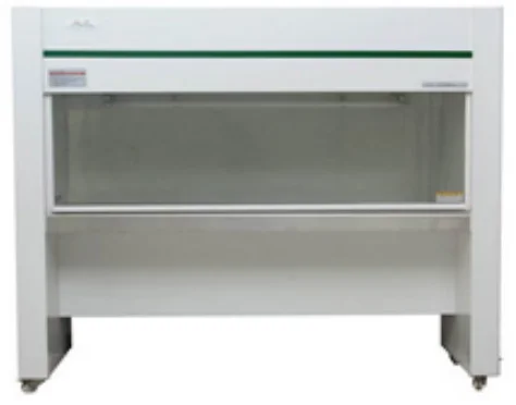
1.Требования к степени чистоты окружающего воздуха для установки выходной головки оптического волокна: 1000 или более строгий класс. Предложения по конфигурации стандартного рабочего места очистки;
2. температура рабочей среды лазера: 10°C–40°C;
3. влажность рабочей среды лазера: 10%-85%;
4. Избегайте конденсационной среды, особые стандарты контроля следующие:

ПРИМЕЧАНИЕ :
◎ Для обеспечения хороших условий эксплуатации лазера, чтобы снизить вероятность выхода из строя из-за конденсации. Мы рекомендуем подготовить кондиционируемое помещение для лазера, чтобы температура в кондиционируемом помещении была ≤ 28 ° C, а относительная влажность ≤ 50%. Водяной охладитель должен быть размещен в другом месте от лазера. Запрещается размещать водяной охладитель в кондиционируемом помещении;
◎ Лазерная головка работает при циркулирующей температуре. Во избежание образования конденсата на лазерной головке необходимо отрегулировать температуру охлаждающей воды внешнего светового тракта до комнатной температуры. Запрещается охлаждать лазерную головку низкотемпературной охлаждающей водой.
6-Структурная схема
Лазерные виды. (Единица измерения: мм)

Глава 5: Руководство по эксплуатации
1-Уведомление
ОСТОРОЖНОСТЬ:
◎ Информацию о правильной электрической мощности см. в Главе 4 «Технические характеристики».
◎ Для проверки соответствия конфигурации периферийной рабочей среды лазера требованиям обратитесь к Главе 2 «Общая информация по технике безопасности».
2-Подключение к электросети
Напряжение питания оптического устройства составляет 360-440 В переменного тока для трехфазного переменного тока. Убедитесь, что фазный и заземляющий провода правильно подключены в соответствии с маркировкой линии. Плохой контакт заземляющего провода может привести к потенциальному повреждению лазера.
Для обеспечения безопасности Maxphotonics рекомендует последовательно подключать автоматический выключатель (воздушный выключатель) и стабилизатор между блоком питания и лазером. Эта электрическая мощность должна находиться в непосредственной близости от блока питания оборудования и легко отключаться.
Если у вас есть вопросы по электропроводке, воспользуйтесь таблицей ниже, чтобы определить ваши электрические характеристики.
| Тип машины/Вт | Напряжение/В переменного тока | Оценено ток /А | Автоматический выключатель /А | Стабилизатор /кВт |
| МФСК-40000 | 400В±10%,3P+PE | 180 | 400А | ≥ 160 |
| МФСК-50000 | 400В±10%,3P+PE | 230 | 400А | ≥ 200 |
Интерфейс с 3 расширениями
ПРЕДУПРЕЖДЕНИЕ:
◎ Выход интерфейса управления лазером не изолирован от опасной части под напряжением, это может привести к поражению электрическим током. Пожалуйста, убедитесь, что оборудование выключено при выполнении подключения. Пожалуйста, убедитесь, что дополнительная изоляция будет предоставлена для предотвращения поражения электрическим током после установки.
Интерфейс Laser CTRL представляет собой высококачественный многоядерный беспроводной интерфейс 55P, который обеспечивает различные сигналы для функционального управления лазером, как описано ниже:

| CTRL ИНТЕРФЕЙС ПРИКОЛОТЬ | ПРОВОЛОКА ЦВЕТ | ФУНКЦИЯ ОПИСАНИЕ | Описание сигнала |
| 1 | Апельсин Черный | EX_LOCK_- | Вход сухого контакта ВКЛ/ВЫКЛ (ВКЛ-нормально, ВЫКЛ-неисправность) |
| 2 | Апельсин | EX_LOCK_+ | |
| 7 | Желтый и черный | КОНТРОЛЬ- | Вход сухого контакта ВКЛ/ВЫКЛ (ВКЛ-свет, ВЫКЛ-не свет) |
| 8 | Желтый | КОНТРОЛЬ+ | |
| 10 | Зеленый | ЭКС_ДА+ | Управляйте выходной мощностью лазера (Аналоговый сигнал 1В-10%, 10В- 100%) Общая ссылка на землю для аналоговые сигналы |
| 11 | Зеленый и Белый | EX_DA- | |
| 13 | Черный и Белый | EX_M- | Управляйте выходной мощностью лазера (Аналоговый сигнал 1В-10%, 10В- 100%) Общая ссылка на землю для аналоговые сигналы |
| 14 | Черный | ЭКС_М+ | |
| 15 | Красный и Белый | EX_EN- | ВЫСОКИЙ: 20 В постоянного тока ≤ В ≤24 В постоянного тока НИЗКИЙ: 0 В постоянного тока ≤ В ≤5 В постоянного тока 5мА≤ I ≤15мА (Включить: HIGH Отключить: LOW) |
| 16 | Красный | EX_EN+ | |
| 27 | Светло-голубой Черный | EMGERNCY1_ ВХОД- | ВЫСОКИЙ: 20 В постоянного тока ≤ В ≤24 В постоянного тока НИЗКИЙ: 0 В постоянного тока ≤ В ≤5 В постоянного тока 5мА≤ I ≤15мА (Аварийная остановка: ВЫСОКАЯ норма: НИЗКИЙ) |
| 28 | Светло-голубой Черный | EMGERNCY1_ ВХОД+ | |
| 31 | Коричневый и Белый | ОШИБКА2 | открытое состояние, когда нет вина, Короткое замыкание, когда есть вина |
| 32 | Коричневый и Белый | ОШИБКА1 |
4-й стартовый шаг
ПРЕДУПРЕЖДЕНИЕ:
◎ Перед использованием убедитесь, что все электрические соединения (включая соединения охлаждающей воды) подключены. Все разъемы должны быть надежно закреплены винтами, если это возможно.
◎ НИКОГДА не смотрите прямо в выходное волокно и обязательно надевайте защитные очки при работе с изделием.
◎ При подключении проводов убедитесь, что лазер обесточен.
Процесс запуска выглядит следующим образом:
1. Запустите чиллер;
2. Снимите торцевую крышку коллиматора;
3. Убедитесь, что торцевая поверхность коллиматора чистая и на ней нет мусора;
4. Убедитесь, что аварийный выключатель включен;
5. Установите ГЛАВНЫЙ ВЫКЛЮЧАТЕЛЬ в положение ВКЛ.;
6. Установите ключ-выключатель на передней панели в положение «ВКЛ»;
7. Нажмите кнопку ПУСК на передней панели.
5-Модуль Описание
Рабочие модули лазера следующие:
1. Непрерывный модуль: излучаемый свет является непрерывным и может использоваться для резки;
2. Импульсный модуль: излучаемый свет пульсирует. Когда частота импульсов больше определенного значения, фактическое приложение используется для управления средней выходной мощностью лазера (регулировка ширины импульса, когда внешнее управление, сигнал модуляции соответствует модулю);
3.Внешнее управление: настройка определенных параметров через программный интерфейс платы.
Временные характеристики внешнего управляющего сигнала:

Описание конкретного времени: аналоговый сигнал мощности 0-10 В подается на лазер по крайней мере за 20 мс раньше времени, модуляция и включение входного сигнала высокого уровня, выключение красного света, выход лазера. Включение снижения сигнала высокого уровня, выход красного света, выключение лазера.
6-Описание программного обеспечения
(1) Программа установки хранится на USB-диске, который упакован случайным образом (версия программного обеспечения не обновляется регулярно, в зависимости от объявления на официальном сайте).

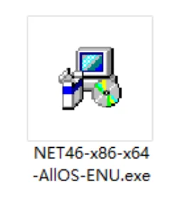
(2) Распакуйте NET4.6.rar, чтобы получить NET46-x86-x64-AllOS-ENU.exe. Дважды щелкните, чтобы запустить установку операционной среды (система Win10 или системы с установленным .NET 4.6 могут пропустить этот шаг).
(3) Распакуйте файл G3-Series (Maxphotonics)-1.0.0.86.rar, чтобы получить G3-Series (Maxphotonics)-1.0.0.86.exe. Дважды щелкните, чтобы запустить и завершить работу мастера установки программного обеспечения для мониторинга (тот, который отмечен «zh», является китайским мастером, а тот, который отмечен «en», является английским мастером).

(4) После завершения установки на рабочем столе появится ярлык.

(5) Дважды щелкните ярлык на рабочем столе, чтобы открыть приложение и войти в следующий интерфейс подключения.
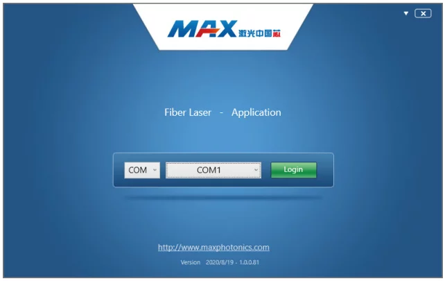
(6) Подключите лазер и ПК с помощью кабеля последовательного порта, который идет в комплекте с произвольным соединением, выберите номер порта, войдите в систему лазера и войдите в следующий интерфейс мониторинга. Примечание: при входе в интерфейс мониторинга,
система выбирает внешний модуль управления по умолчанию. Внешняя модуляция/включение/управление сигналом DA.
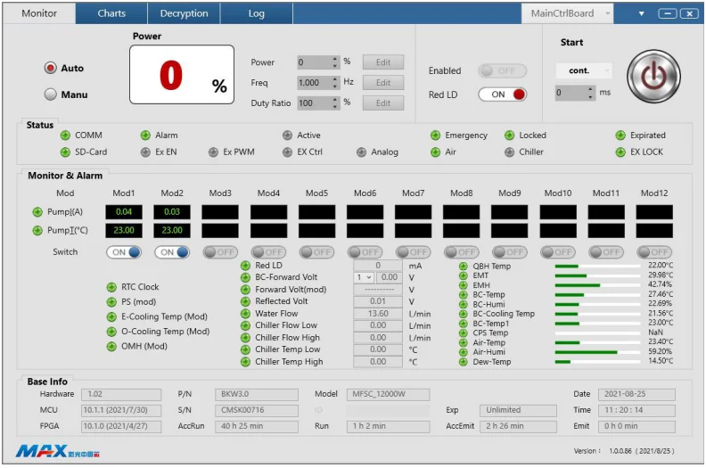
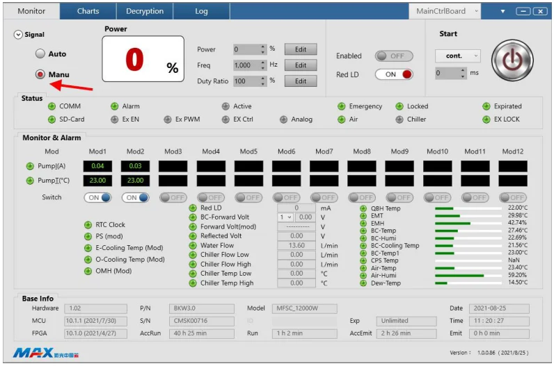
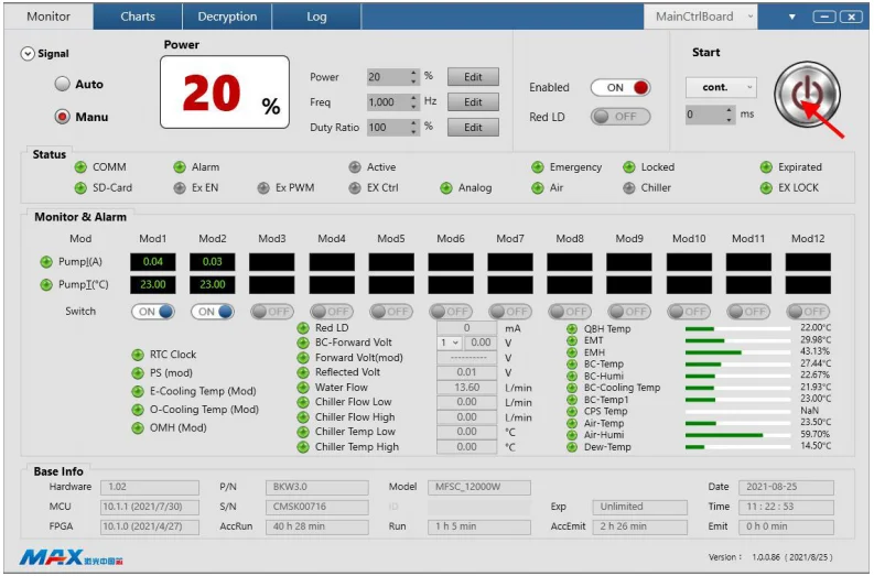
(7) Внутренний модуль управления управляет лазером. (Щелкните, чтобы выбрать внутренний модуль управления).
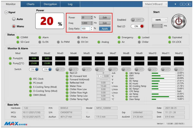
(8) Отредактируйте и установите мощность лазера / частоту / рабочий цикл.
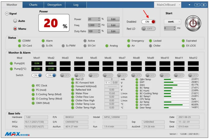
(9) Щелкните, чтобы включить сигнал включения хост-компьютера.
(10) Щелкните, чтобы включить верхнюю кнопку запуска лазера компьютера.
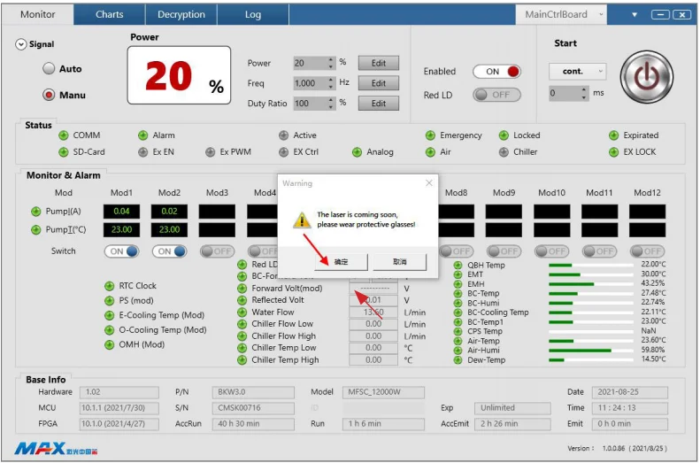
(11) Нажмите «Да» в окне запроса, чтобы включить лазер.
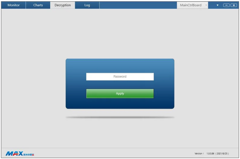
(12) Интерфейс дешифрования.
Совет: Подробную информацию об установке и использовании программного обеспечения см. в руководстве по программному обеспечению на диске U.
7-Список ошибок
Точки оповещения о неисправностях, устанавливаемые лазером, включают в себя:
Сигнализация PD переднего света
Меры защиты:
Прекратите подачу питания на основной источник питания и выключите лазер.
Возможные причины:
Лазер внутри не обнаруживает лазер.
Решения :
1. Перезапустите лазер без лазера, проверьте наличие красного света. Если красного света нет, обратитесь в службу поддержки клиентов Maxphotonics;
2.Если горит красный свет, проверьте, может ли соответствующий модуль включить лазер. Проверьте, есть ли у модуля постоянный ток и выходное напряжение.
нормальный.
Очень сильная подсветка будильника
Меры защиты:
Прекратите подачу питания на основной источник питания и выключите лазер.
Возможные причины:
Модуль объединения лучей обнаруживает, что обратный свет слишком сильный.
Решения:
1. Проверьте положение фокуса лазера;
2.Проверьте, расположен ли материал горизонтально;
3.Проверьте, является ли материал сверхвысокоотражающим;
4. Проверьте, превышает ли толщина материала стандарт и не может ли прорезаться сигнализация;
5. Выключите лазер, подождите 3–5 минут, перезапустите лазер и включите лазер.
Сигнализация температуры насоса
Меры защиты:
Прекратите подачу питания на основной источник питания и выключите лазер.
Возможные причины:
Температура накачки лазерного модуля слишком высокая, срабатывает аварийный сигнал температуры.
Решения:
Выключите лазер, проверьте, нормальны ли скорость потока воды в охладителе и температура воды, а также не засорен ли водопровод. После завершения
осмотр, перезапустите лазер и лазер вернется в норму. Если он не может вернуться в норму. Обратитесь в службу поддержки клиентов Maxphotonics.
Установка сигнализации QBH
Меры защиты:
Прекратите подачу питания на основной источник питания и выключите лазер.
Возможные причины:
Плохой контакт выходной головки QBH с контактом режущей головки.
Решения:
Выключите лазер, проверьте выходную головку лазера QBH и режущую головку, затем установите их заново.
Сигнализация аварийной остановки
Меры защиты:
Прекратите подачу питания на основной источник питания и выключите лазер.
Возможные причины Нажат выключатель аварийной остановки.
Решения:
Переведите аварийный останов в нормальное положение и перезапустите лазер.
Сигнализация потока воды
Меры защиты:
Прекратите подачу питания на основной источник питания и выключите лазер.
Возможные причины:
Водоохлаждающая машина вышла из строя, что привело к снижению расхода воды.
Решения:
Выключите лазер, проверьте, нормальны ли расход воды в охладителе и температура воды, не засорен ли водопровод. После завершения проверки перезапустите лазер, и лазер вернется в нормальное состояние.
Сигнализация ненормальной связи
Меры защиты:
Прекратите подачу питания на основной источник питания и выключите лазер.
Возможные причины:
Передача сигнала между линией связи отдельного модуля и основным модулем отсутствует.
Решения:
1. Проверьте, не ослаблена ли сигнальная линия, соединяющая одиночный модуль и основной модуль.
2.Проверьте, нормально ли включается питание отдельного модуля, горит ли красный индикатор и нормально ли работает выходное напряжение вспомогательного источника питания.
Сигнализация максимального тока
Меры защиты:
Прекратите подачу питания на основной источник питания и выключите лазер.
Возможные причины:
Рабочий ток источника одномодульного насоса превышает максимальный предел.
Решения:
1. Перезапустите после выключения лазера, проверьте, нормально ли он работает; если все в порядке, используйте его как обычно;
2.Если сигнализация максимального тока продолжает срабатывать, возможно, трубка привода MOS вышла из строя в одном модуле. Вам необходимо немедленно выключить лазер и обратиться в службу поддержки клиентов Maxphotonics.
Сигнализация пластины водяного охлаждения электрического модуля
Меры защиты:
Прекратите подачу питания на основной источник питания и выключите лазер.
Возможные причины:
Температура водяного модуля слишком высокая, и срабатывает аварийный сигнал температуры.
Решения:
Выключите лазер, проверьте, нормальны ли скорость потока воды в охладителе и температура воды, а также не засорен ли водопровод. После завершения проверки перезапустите лазер, и лазер вернется в нормальное состояние. Если он не может вернуться в нормальное состояние, свяжитесь со службой поддержки клиентов Maxphotonics.
Сигнализация температуры охлаждающей пластины водоохладителя комбайнера
Меры защиты:
Прекратите подачу питания на основной источник питания и выключите лазер.
Возможные причины:
Температура водяного модуля слишком высокая, и срабатывает аварийный сигнал температуры.
Решения:
Выключите лазер, проверьте, нормальны ли скорость потока воды в охладителе и температура воды, а также не засорен ли водопровод. После завершения проверки перезапустите лазер, и лазер вернется в нормальное состояние. Если он не может вернуться в нормальное состояние, обратитесь в службу поддержки клиентов Maxphotonics.
ПРИМЕЧАНИЕ:
◎ Вся информация о лазерной тревоге, будет иметь соответствующее напоминание на дисплее программного обеспечения мониторинга: пожалуйста, обратите внимание! Если у вас есть какие-либо вопросы, пожалуйста, свяжитесь с нашими сотрудниками службы поддержки клиентов.
Глава 6: Техническое обслуживание и ремонт
1-Инструкции по техническому обслуживанию
Перед подключением разъема лазерного волокна необходимо проверить наличие пыли, грязи и повреждений торцевой поверхности. Использование грязных или нечистых разъемов оптоволокна может привести к серьезному повреждению лазера. Maxphotonics не несет ответственности за повреждения лазера, вызванные использованием нечистых разъемов оптоволокна. Если разъем оптоволокна был подделан в частном порядке, гарантия на оборудование больше не распространяется.
Для очистки оптоволоконного разъема вам понадобятся следующие материалы:
1.Резиновые неопудренные перчатки или напальчники;
2. Безворсовые салфетки и/или тампоны для чистки оптики;
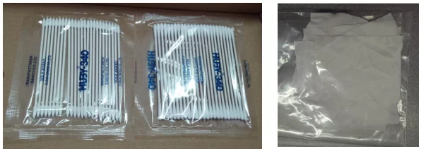
3. Безводный этанол (Оптический уровень, чистота >99,5%);
4. Сжатый воздух (без масла и воды) или деревянный стержень, обмотанный двухслойной клейкой лентой;
5. Масштабный микроскоп (может увеличиваться в 20 раз и более).

ВАЖНЫЙ:
◎ Обязательно надевайте резиновые перчатки без пудры во время этой процедуры очистки! Настоящим заявляется, что повреждение волоконного соединителя может произойти из-за неправильного обращения, использования неправильных процедур очистки или химикатов для очистки. Это не покрывается гарантией Maxphotonics.
2-Внешний осмотр
1. Экологические требования
Очистка LOE и установка режущей головки должны выполняться на рабочем столе для очистки в чистом помещении, для класса очистки от пыли требуется класс 1000, а эталонный рабочий стол для очистки должен быть следующим:
2. Эксплуатационные процедуры
1. Выключите питание лазера и установите ключ-переключатель в положение «ВЫКЛ»;
2. Поверните черную защитную гильзу соединителя по часовой стрелке, поместите ее под 20-кратный микроскоп и очистите проверяемую поверхность, а также проверьте, соответствует ли внешний вид кварцевого стержня стандарту внешнего вида (ссылка 2.2.5);
3. Если частиц пыли нет или они соответствуют стандартам внешнего вида, наденьте черную защитную оболочку на разъем;
4. Если обнаружено, что частицы пыли превышают стандартные требования к внешнему виду, то очистите их в соответствии с требованиями шага 3;
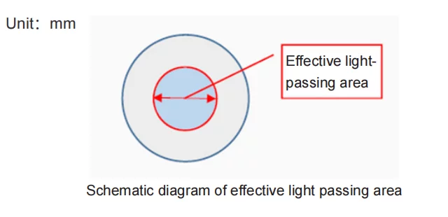
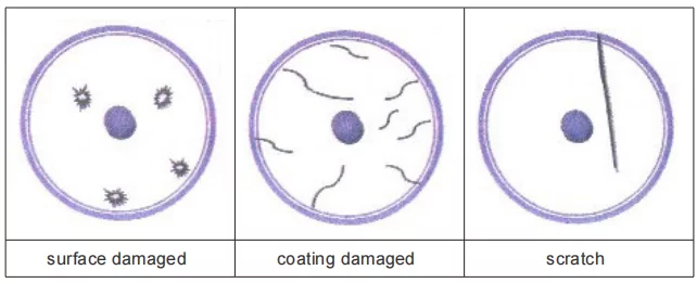
5. Стандарты внешнего вида приведены в таблице ниже:
| Власть | Кварцевый стержень | |
| Эффективная площадь пропускания света (в пределах φ3мм) | Неэффективная площадь пропускания света (внешний φ3мм) | |
| 4000Вт-30кВт | Диаметр язвины: Не разрешено Ширина царапины: Не разрешено | Диаметр язвины: ≤ 0,1 Ширина царапины: ≤ 0,005 |
| 2000Вт-4000Вт | Диаметр язвины: ≤ 0,05 Ширина царапины: ≤ 0,002 | Диаметр язвины: ≤ 0,1 Ширина царапины: ≤ 0,005 |
| Менее 2000 Вт (отдельный модуль) | Диаметр язвины: ≤ 0,1 Ширина царапины: ≤ 0,005 | Диаметр язвины: ≤ 0,1 Ширина царапины: ≤ 0,01 |
3-Процедуры очистки
1. Выключите питание лазера и установите ключ-переключатель в положение «ВЫКЛ».
2.Очистка защитных линз тампонами
1. Поверните черную защитную оболочку соединителя по часовой стрелке, поместите внутреннюю или внешнюю поверхность под микроскоп 20 раз и сделайте ее прозрачной. После тщательного наблюдения определите конкретное положение частиц пыли, откройте крышку бутылки со спиртом и слегка нажмите на горлышко бутылки со спиртом, чтобы небольшое количество спирта вытекло, полностью погрузите круглый ватный тампон в спирт, а затем слегка протрите ватный тампон, чтобы удалить излишки спирта. Используйте ватный тампон, чтобы вытереть частицы пыли прямо в направлении тела оператора.
Усилие должно быть легким. После каждого протирания ватный тампон можно повернуть на 180°, а затем протереть другой стороной. После протирания 2 раза ватный тампон выбрасывается. Обратите внимание, что он не должен вращаться. Или протирайте вперед и назад, чтобы предотвратить загрязнение других участков частицами пыли или непосредственное царапание поверхности ватными тампонами. После всей очистки необходимо снова осмотреть под микроскопом, чистая ли поверхность.
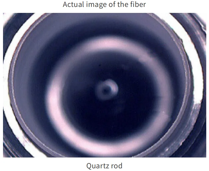
Торцевая поверхность может быть повреждена.
2. Проверьте внутреннюю стенку защитной направляющей трубки на наличие явных посторонних предметов в микроскопе. Если посторонние предметы можно очистить с помощью двухстороннего клея-карандаша, то используйте ватный тампон, чтобы смыть спирт для дальнейшей очистки.
После того, как защитная направляющая трубка высохнет, наденьте ее непосредственно на соединитель.
3.Способ очистки кварцевых стержней
Если вы обнаружили, что внутренний кварцевый стержень запылился или загрязнился, вы можете открыть линзу, чтобы очистить его. Конкретные шаги следующие:
1. Поверните черный защитный кожух, пылезащитный колпачок и защитную линзу по часовой стрелке, сначала протрите окружность и резьбовую поверхность всей линзы соединителя салфеткой для чистки оптики и спиртом;

2.Поместите кварцевый стержень под 20-кратный микроскоп и очистите его. После тщательного наблюдения определите конкретное местоположение частиц пыли и очистите в соответствии с методом 3.2.1. Для частиц пыли на боковой стороне плавленого кварцевого стержня используйте заостренный ватный тампон для очистки вдоль окружной поверхности.
После всей очистки, подтвердите под микроскопом, является ли он чистым, включая скошенную область. Наконец, оберните его на столе нетканым материалом, а затем продолжайте другую работу, чтобы предотвратить повторное загрязнение пылью торцевой поверхности и боковой поверхности стержня из плавленого кварца;
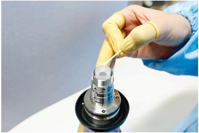
3. Вдоль волокон поверхности металлической части осторожно поверните линзу обратно к металлической части и убедитесь, что она на месте. Наденьте черную защитную оболочку на разъем.

ВАЖНО:
◎ Не используйте повторно безворсовые салфетки или тампоны для чистки оптики;
◎ Не прикасайтесь к защитной линзе оптоволоконного разъема;
◎ Не дуйте напрямую, иначе будет занесена новая грязь;
◎ Не прикасайтесь пальцами к кончику чистящего тампона;
◎ Перед установкой защитного чехла и рукава необходимо произвести очистку;
◎ Никогда не направляйте воздух непосредственно на поверхность, так как вы можете впитать
загрязняющие вещества на поверхность. Всегда дуйте на поверхность;
◎ Если оптоволоконный разъем не удалось сразу установить в оптическую систему, закройте его защитным колпачком, очищенным сжатым воздухом;
◎ Обязательно работайте в чистой среде класса 1000.
Установка и меры предосторожности режущей головки 4-LOE
1.Этапы установки
1. Головка LOE с внутренней резьбой закреплена на режущей головке, а головка LOE с внутренней резьбой повернута по часовой стрелке в фиксированное положение;
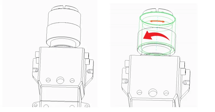
2. Вставьте очищенный штекер LOE в соответствующий фиксированный гнездовой разъем.
Во избежание скопления пыли на торцевой поверхности LOE и внутренней части режущей головки, пожалуйста, убедитесь, что LOE и режущая головка находятся в горизонтальном положении;
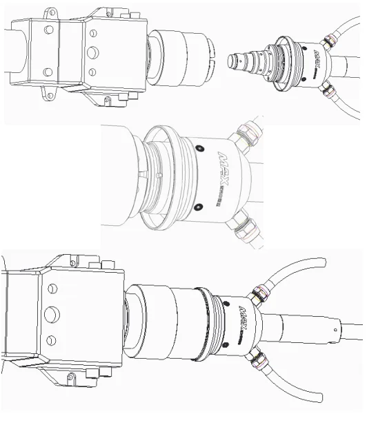
3.Поверните штекер по часовой стрелке до фиксированного положения.
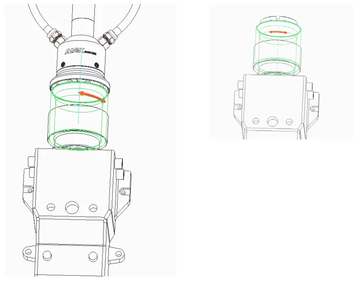
2.ВАЖНО
◎ Перед установкой женской головки необходимо снять мужскую головную линзу LOE;
◎ После снятия линзы необходимо очистить кварцевый стержень и резьбу неподвижного элемента линзы;
◎ Головка вставки LOE «папа» и «мама» должны быть отцентрированы, чтобы не повредить кварцевый стержень;
◎ Весь рабочий процесс должен осуществляться в среде со 100-уровневой очисткой от пыли.
Глава 7: Руководство по разборке
1-Шаги распаковки
Лазер относится к точным ценностям, поэтому Maxphotonics рекомендует следующие шаги по распаковке упаковочной коробки. Упаковочный лист прилагается к коробке.
После распаковки проверьте комплектацию согласно упаковочному листу.
Пожалуйста, сохраните все предметы после распаковки, чтобы исключить будущую транспортировку или хранение.
На следующем рисунке показаны шаги по снятию коробки:
1. Поместите коробку с лазерным оборудованием на устойчивое место, например, на толстый пол или большую платформу.
2. Мы рекомендуем вам использовать толстую отвертку, чтобы поддеть пластиковый зажим, снять пластиковую застежку, а затем снять верхнюю крышку.
3. Поднимите верхнюю балку и снимите ее, стараясь не поцарапать верхний трос.
4. Снимите верхнюю пену и возьмите аксессуар.
5. Выполните второй шаг, чтобы снять четыре боковые панели в следующем порядке: длинные края -> короткие стороны -> еще одна короткая сторона -> еще одна длинная сторона.
6. Снимите натяжной ремень и полиэтиленовый пакет, обратите внимание на направление затяжки храпового механизма и способ открытия затяжки ремня:
- Нажмите и удерживайте стопорное кольцо.
- Поворот и затягивание виселицы на 180°
- С силой вытяните ремни
7. Используйте вилочный погрузчик или кран, чтобы поднять лазер и переместить его в указанное место.
Если клиентам необходимо переупаковать товар, выполните следующие действия.
1. Установите поддон и очистите его, затем поместите натяжной ремень и пропустите его через нижние пазы с обеих сторон поддона.
2. Используйте вилочный погрузчик, чтобы поднять продукт на определенную высоту, переместите поддон вниз и медленно разместите продукт. При размещении продукта обратите внимание на направление продукта, как показано на рисунке.
3. Наденьте полиэтиленовый пакет, затяните натяжной ремень и отделите бумажные углы между продуктом и натяжным ремнем. Всего 4 бумажных угла. Обратите внимание на использование натяжного ремня:
- Найдите положение вала с прорезью и пропустите ремень снизу вала с прорезью;
- Затяните ремень и поверните его обратно в положение оси паза;
- Ремни изношены и
- Затянул ремни;
- Встряхните ручку вперед и назад, чтобы
4. Соберите боковую панель, вставьте пластиковую пряжку в прорезь и закрепите ее. Последовательность сборки: длинная сторона -> короткая сторона -> еще одна короткая сторона -> еще одна длинная сторона.
5. Соберите верхнюю опору и верхнюю пену, обращая внимание на то, чтобы верхняя опора подвешивала боковые панели.
6. Соберите верхнюю крышку и застегните все пластиковые пряжки.
ПРИМЕЧАНИЕ:
◎ Если после получения товара вы обнаружили какие-либо повреждения внешней упаковки или внутренних компонентов, немедленно свяжитесь с Maxphotonics или вашим местным представителем.
◎ Лазер оснащен осушителем. Когда окружающая температура и влажность слишком высоки, лазер будет иметь процесс предотвращения конденсации росы и осушения (около 30 минут). Конденсат будет вытекать из нижнего отверстия корпуса.
◎ При выключении лазера следует также выключить водяной охладитель, чтобы предотвратить образование конденсата из-за чрезмерной разницы температур.
РЕКОМЕНДАЦИЯ:
Измените рабочую температуру или влажность лазера, чтобы лазер не достигал точки росы (например, установите лазер в кондиционируемом помещении).
| Нет. | Названия фитингов | Описание | Единица | Количество |
| 1 | Волоконно-оптический лазер | MFSC-XXX | ПК | 1 |
| 2 | Последовательный кабель USB-RS232 | БЛТ | 1 | |
| 3 | Кабель | БЛТ | 1 | |
| 4 | Ключ | ПК | 2 | |
| 5 | U-диск | ПК | 1 | |
| 6 | Зажим | ПК | 2 | |
| 7 | RS232 (внешний) | БЛТ | 1 | |
| 8 | Кабель-адаптер внешнего управления клиента | БЛТ | 1 | |
| 9 | Внешняя линия управления | БЛТ | 1 | |
| 10 | Непрерывный внешний интерфейс управления страховой совет PCBA | ПК | 1 | |
| 11 | Супертонкая салфетка для удаления пыли (2*2) | ПК | 6 | |
| 12 | Пробоотборная трубка QBH для водопровода | БЛТ | 1 | |
| 13 | Лазерная трубка для измерения воды | БЛТ | 1 | |
| 14 | Заостренный ватный тампон | Сумка | 1 | |
| 15 | Круглая ватная палочка | Сумка | 1 |
Глава 8: Техническое обслуживание и ремонт
1-Заметки по техническому обслуживанию
ОСТОРОЖНОСТЬ :
◎ Внутри нет обслуживаемых оператором деталей. По всем вопросам обслуживания обращайтесь к квалифицированному персоналу Maxphotonics.
◎ Для обеспечения возможности выполнения ремонта или замены в рамках гарантии и полного соблюдения ваших интересов, пожалуйста, подайте заявку в Maxphotonics или местному представителю после обнаружения неисправностей. После получения нашего разрешения вам необходимо упаковать продукт в подходящую упаковку и вернуть его.
◎ При обнаружении повреждений после получения товара вам следует сохранить доказательства, чтобы иметь возможность предъявить свои права грузоотправителям.
ВАЖНЫЙ :
◎ Не отправляйте продукцию в Maxphotonics без RMA, в противном случае она будет возвращена в соответствии с отказом. Возникающие в результате убытки несет клиент; для обеспечения своевременной обработки возвращаемой машины клиент должен отправить неисправную машину по указанному адресу Maxphotonics.
Если гарантийный срок или область действия гарантии на изделие истекли, заказчик несет ответственность за оплату расходов на ремонт. Конкретные расходы включают стоимость запасных частей, оплату услуг рабочей силы, а также расходы на проезд, проживание и другие расходы, связанные с обслуживанием на месте.
ИЗМЕНЯТЬ :
◎ Мы имеем право изменять любой дизайн или структуру нашего продукта, и информация может быть изменена без предварительного уведомления.
2-Услуги
Если у вас возникли проблемы с безопасностью, настройкой, эксплуатацией или обслуживанием, внимательно прочтите это «Руководство пользователя» и строго следуйте инструкциям по эксплуатации. По всем остальным вопросам обращайтесь в отдел обслуживания клиентов.


