Оглавление
Скорость обратного хода ползуна низкая, что приведет к снижению эффективности производства гидравлический листогибочный пресс и влияют на эффективность производства предприятия. В данной работе анализируются причины выхода из строя гидравлический листогибочный пресс, проводит комплексную диагностику и устраняет неисправность, что дает новое представление о предотвращении соответствующих неисправностей в будущем и имеет практическое значение для повышения эффективности производства предприятия.
Технические параметры
Гидравлический листогибочный пресс модели wc67y-125t /3200, номинальное давление 1250 кН, длина стола 3200 мм, ход ползуна 120 мм, скорость хода ползуна вниз/вниз/вниз быстрая 36/9/45 мм/с, максимальное рабочее давление гидравлической системы 20 МПа.
Принцип работы гидравлического листогибочного пресса

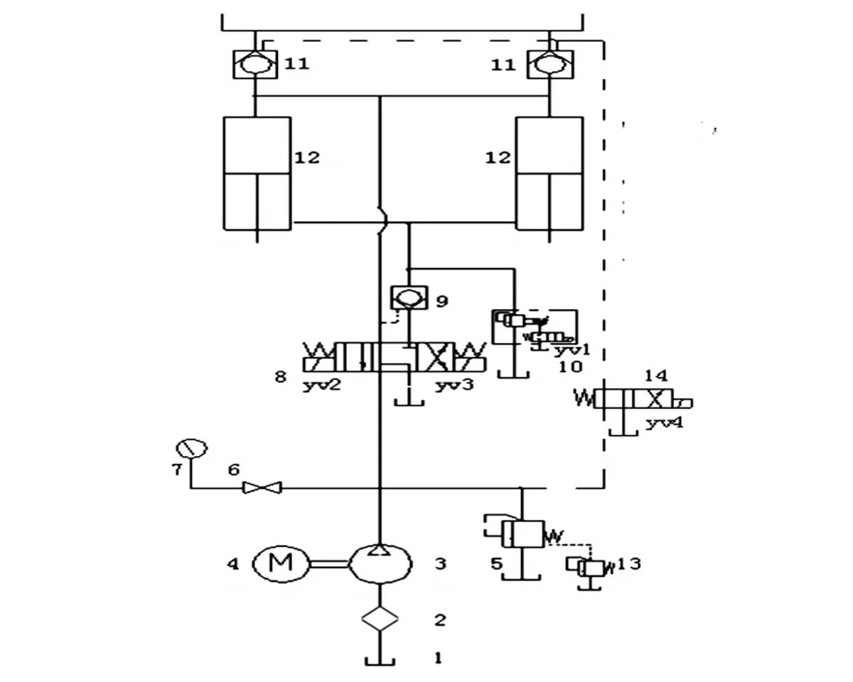
Благодаря взаимодействию гидравлической системы трансмиссии и электрической системы управления этот гидравлический листогибочный пресс может заставить ползунок реализовать рабочий цикл быстрого, медленного, поддержания давления, сброса давления и обратного хода, чтобы соответствовать требованиям гибки заготовки.
1) Быстро сползите вниз.
Соленоидный реверсивный клапан 8 YV2 электричество, электромагнитный перепускной клапан 10 YV1 электричество. Впуск масла: выход масла из масляного насоса 3 через клапан 8 в верхнюю камеру двух масляных цилиндров 12, толкает шток поршня двух масляных цилиндров, чтобы привести ползун вниз. Управляйте маслом в масляном контуре, чтобы открыть односторонний клапан управления жидкостью 9 и клапан заполнения жидкостью 11. В процессе опускания ползуна клапан 11 осуществляет высокое заполнение маслом, чтобы реализовать быстрое опускание ползуна. Возврат масла: масло из нижней камеры двух масляных цилиндров возвращается в масляный бак через электромагнитный перепускной клапан 10 раз.
2) Замедлите ползунок.
Электромагнитный клапан 8 YV2 питание, два четырехходовых клапана 14 YV4 питание. Масло; Выход масла из масляного насоса 3 через клапан 8 в верхнюю камеру двух масляных цилиндров 12, толкает шток поршня двух масляных цилиндров, чтобы привести ползун вниз. Управляйте маслом в масляном контуре, чтобы открыть гидравлический управляющий односторонний клапан 9. Возврат масла: масло из нижней камеры двух масляных цилиндров 12 течет обратно в масляный бак через односторонний клапан с жидкостным управлением 9 и электромагнитный направляющий клапан 8.
3) Сохранение напряжения системы.
Управляемый реле времени KTI, удержание давления ползуна может осуществляться для достижения формовки и гибки заготовки. Время удержания давления может регулироваться.
4) Сброс давления в системе.
Для уменьшения обратного воздействия на обратный ход ползунка, Yv2 потеряет питание на короткое время перед обратным ходом ползунка. Сначала осуществляется сброс давления в системе, а затем обратный ход ползунка. Время сброса давления можно регулировать.
5) Обратный ход слайдера.
Соленоидный реверсивный клапан 8 мощности YV3. Впуск масла: выход масла из масляного насоса 3, через соленоидный направляющий клапан 8 и гидравлический управляющий односторонний клапан 9 до нижней камеры двух цилиндров 12, чтобы вытолкнуть два цилиндра, шток заглушки будет приводить ползун назад.
В то же время, контролируйте масло в масляном тракте через двухпозиционный четырехходовой реверсивный клапан 14, чтобы открыть гидравлический регулирующий одноходовой клапан 11, чтобы подготовить возврат масла из верхней камеры. Возврат масла: масло в верхней камере 12 цилиндров напрямую возвращается в масляный бак через гидравлический регулирующий одноходовой клапан 11, чтобы реализовать быстрый возврат ползуна.
6) Регулирование рабочего давления системы.
В зависимости от давления, требуемого деталями гибочной машины, его можно реализовать путем регулировки ручки дистанционного клапана регулировки давления 6. После регулировки колпачок за ручкой должен быть заблокирован, а клапан высокого давления 5 должен быть отрегулирован перед отправкой с завода. Максимальное рабочее давление системы не должно превышать 20 МПа.
Анализ причин отказов
Анализируя принципиальную схему работы и рабочий процесс гидравлической системы этого гидравлического листогибочного пресса, можно выделить следующие причины медленной скорости возврата ползуна: 1) гидроцилиндр и поршень не герметичны, что приводит к взаимной утечке между верхней и нижней камерами. 2) электромагнитный перепускной клапан 10 заблокирован и закрыт неплотно. 3) односторонний клапан гидравлического управления 9 не установлен на место. 4) засорение того же демпфирующего отверстия сердечника одностороннего клапана гидравлического управления 11 приводит к плохому возврату масла. 5) сердечник 8 электромагнитного реверсивного клапана сильно изношен, что приводит к отказу реверсирования.
Диагностика неисправностей и меры по их устранению
1) Проанализируйте рабочее состояние гидравлического листогибочного пресса.
Скользящий блок в норме для быстрого прижима листового материала, и нет утечки на внешней поверхности гидроцилиндра. Поэтому можно исключить, что верхняя и нижняя полости гидроцилиндра перетекают друг в друга, а односторонний клапан управления гидроприводом 9 не находится на месте
2) Отрегулируйте давление электромагнитного перепускного клапана 10, когда цилиндр пересечения давления совершает обратный ход, и показания манометра будут соответственно регулярно меняться, так что производительность электромагнитного перепускного клапана 10 будет нормальной.
3) Проверьте и проверьте гидравлический регулирующий односторонний клапан 11.
В демпфирующем отверстии сердечника клапана нет засорения, и клапан 11 открывается и закрывается на месте с нормальной производительностью.
Проверяя, сравнивая и проверяя вышеперечисленные условия по одному, мы можем в принципе исключить их влияние на неисправность, поэтому мы можем предварительно определить, что неисправность электромагнитного распределителя 8 является причиной медленной скорости возврата гибочной машины.
В результате капитального ремонта электромагнитного распределителя 8 было обнаружено, что поверхностный износ сердечника электромагнитного распределителя 8 оказался серьезным, что привело к блокировке электромагнитного распределителя 8 в процессе возврата электричества YV3.
Гидравлическое масло необходимо для электромагнитного направляющего клапана и гидравлического управления в одном направлении, а также для толкателя штока 12 нижней вены с 9 по 8 цилиндра, который приводит в движение ползун на обратном пути, поскольку потеря сердечника клапана 8 серьезна, направленное управление не достигает назначенного положения, толкает ползунок, а обратное давление гидравлического масла недостаточно, в результате чего скорость возврата медленная.
Замените электромагнитный распределитель 8, проведите пробную обработку, скорость обратного хода увеличится, и 1 будет работать нормально.
Заключение
Подводя итог, можно сказать, что для устранения неисправностей гидравлической системы необходимо освоить конструкцию и принцип работы гидравлической системы и связанных с ней гидравлических компонентов, иметь глубокое понимание работы каждого компонента гидравлического листогибочного пресса во время соответствующей работы гидравлического оборудования и точно выявлять неисправности оборудования, наблюдая за неисправностями оборудования.


