Creating an operation manual for a swing beam shearing machine involves providing detailed instructions on how to safely and effectively operate the equipment. Here's a structured outline for such a manual:
Table of Contents
Standard Features of the Hydraulic Swing Beam Shearing Machine
The hydraulic swing beam shearing machine is designed for cutting metal-steel plates, with a capacity based on a plate strength of 450N/mm2.
Please adjust the plate thickness if cutting other materials with different strengths.
The machine features a sheet plate welded structure, which provides for easy operation and reliable performance.
Cutting is powered by hydraulic pressure, and the return is controlled by a nitrogen gas cylinder, which helps to protect the machine from overload.
The machine can be equipped with a digital display system or numerical control system, as requested by the customer.
A blade gap indicator is also provided for convenient and prompt adjustments.
The machine is equipped with an alignment device with lighting, and the cutting stroke can be adjusted to improve the efficiency of cutting narrow plates.
Additionally, front support arms and a back gauge are provided. The back gauge is mechanically transferable and its position can be displayed numerically or controlled by an NC controller through encoders, with micro-adjustment by a hand-wheel. The front supporting arms are equipped with rulers.
A rolling material support ball is provided on the worktable to minimize fishtailing with sheet bars and reduce friction resistance.
A safety fence has been installed to ensure safe operation.
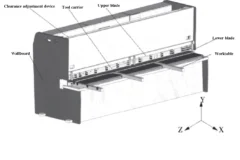
Frame of the Hydraulic Swing Beam shearing Machine
Machine frame
Steel-welded plate with high rigidity features two cylinders fixed on the left and right vertical pole.
A vice cut-board is installed on the worktable for convenient adjustment of the lower cut-board, ensuring that the gap between the upper and lower cut-boards is aligned. A feed ball is also installed on the worktable for convenient and fast operation.
Cutting frame
The high-rigidity welded plate is supported at the eccentric socket (9) and driven by the left and right cylinders and the stroke cylinder to complete the cutting process through pendulum repetition. The vertical surface of the up-cut support is curved to maintain the alignment of the gap between the up-cut and low-cut.

Pressure device (Hold down)
It consists of pressure feed cylinders installed on the support board in front of the machine frame. The oil flow in the pressure feed cylinder creates pressure that pushes down against the pull force of the stress spring (18), securing the press plate tightly. After cutting is complete, the cylinders are reset by the pull force of the stress spring. The pressure increases with the thickness of the plate.
Front gauge and back gauge
Front gauge:
The worktable is equipped with a valve display on the ruler, allowing the mobile bar to be adjusted to the desired valve. Cutting thin steel plates can be conveniently done on the front gauge. The back gauge (refer to picture 5) is fixed on the up-cut board and moves up and down with it.
The back gauge is adjusted by a 0.55Kw motor, which reduces the torque through a gear and drives the control rod. By pressing the “+” or “-” button, the gauge can be adjusted forward or backward. In case the desired valve cannot be achieved through mechanical adjustment, the hand-wheel (50) can be turned to achieve the required valve, making the adjustment of the back gauge both convenient and reliable.
The standard range of the back gauge is 20-750mm. If the length of the cutting plate is longer than the maximum distance of the back gauge, the back gauge (43) can be removed to its minimum position and the board can be lifted up using the inclined surface of the support frame (47), allowing for cutting of any length of plate. (Refer to Fig. 4)
Installation of Swing Beam Shearing Machine
Packing / Shipment of hydraulic shearing machine
All machines leaving the factory are packaged with a squaring arm and foot panel tied to the hand guard. The working tools and an operating manual are packaged into one box.
All exposed surfaces of the machine are coated with a rust inhibitor, which can be easily removed with kerosene or a solvent.
Lifting the hydraulic shearing machine
Use only approved and safe wire ropes to lift this machine from the two lifting points located at both sides of the machine. (See Figure 5)
Foundation
All our shears are designed to be installed on a foundation. Please refer to the attached foundation drawing for details.
Installation
This hydraulic shearing machine must be properly leveled for optimal cutting performance. This can be achieved by using a high-quality leveling gauge on the plate hold-down area.
Before leveling, ensure that you have five base plates (measuring at least 150 x 150 x 9mm) placed beneath the machine’s feet to prevent the leveling screws from digging into the concrete floor.
Once the machine is leveled, secure its position by filling the space under and around its feet with a cement grout mixture.
Electrical Installation
Make sure that the local power supply is compatible with this hydraulic shearing machine before turning on any electrical power.
Connect the power cable to the bottom left side of the electrical panel. Some machines may require a neutral wire.
Adjustment of the Swing Beam Shearing Machine

Adjust the gap between blades of the hydraulic shearing machine
The blade gap is crucial to both the quality of the cutting and the lifespan of the blades. Please adjust according to the gap adjustment table below.
Adjust the gap between blades
To adjust the gap (refer to Picture 2), you need to loosen the tight screw (4), then turn the handwheel (3) to the desired value, which should be calculated based on the thickness of the plate, and finally tighten the screw (4).
There is a ball valve (located on the right side of the machine, outside of the cylinder) that is used to measure the clearance gap between the upper and lower blades.
For more details: in manual mode, when the cutting frame reaches the bottom dead spot, quickly close the oil circuit, causing the cutting frame to remain at the bottom dead spot. Then, slowly turn on the ball valve, causing the cutting frame to move up step by step along the entire stroke. This will allow you to measure the clearance value of the gap between the blades.
Operation of Hydraulic Shearing Machine
Preparation of Machine
(1) Remove the squaring arm and foot pedal from the hand guard area. Secure the squaring arm to the left-hand side of the machine table using bolts and the two side holes. The arm should be close to the electrical panel.
(2) Clean the components of any dirty oil, being careful to ensure that the ball valve is in the open position.
(3) Lubricate all necessary areas.
(4) Fill the oil tank with 200L of HL46 hydraulic oil for each machine under the 12mm model.
(5) Connect the earth line, turn on the power, and check the operation of all electrical components.
Starting the Machine
(1) Press the ‘START’ button and release.
(2) The ‘motor on’ indicator light should turn on.
(3) Change the mode selector from ‘MAN’ to ‘AUTO.’
(4) Step on the foot switch, causing the cutting frame to descend and make a cut.
(5) If the cutting frame does not descend, it is likely that the motor is running in the wrong direction. Turn off the power and reverse either of the two phase wires to restart the motor.
(6) The top blade carrier will rise and stop when it reaches the limit switch.
Motorized Back Gauge
(1) The motorized back gauge display should be accurately set in the factory and should correspond to the distance from the back gauge bar to the cutting edge.
(2) Press the ‘+’ button to bring the back gauge bar to the rear. The reading will increase and stop when it reaches the maximum travel limit switch L/S 3.
(3) Press the ‘-‘ button to bring the back gauge bar to the front. The reading will decrease and stop when it reaches the minimum travel limit switch L/S 4.
(4) The parallelism of the back gauge should be set in the factory, but can be calibrated as needed.
(5) Move the back gauge bar to the rear to remove the anti-rust coating before cutting.
Note:
(1) The pressure table should be on during cutting, and the pressure should be checked if it appears to be incorrect. The overflow valve may need to be adjusted.
(2) If any unusual noise or overheating of the oil tank occurs during operation, the machine should be stopped immediately. The temperature of the oil tank should not exceed 60°C.